 Hello! now
 tms@lcdchip.com



Analog Devices Inc./Maxim Integrated MAX17651AZT+T

- Part No.:
- MAX17651AZT+T
- Manufacturer:
- Analog Devices Inc./Maxim Integrated
- Package:
- SOT-23-6 Thin, TSOT-23-6
- Description:
- IC REG LIN POS ADJ 100MA TSOT23
- Quantity:
Unit Price:$0
Ext Price:$0
- Payment:

- Shipping:


Product Details
MAX17651AZT+T - 60 V, 100 mA Adjustable Linear Regulator
Analog Devices MAX17651AZT+T is a high-voltage, low-quiescent-current adjustable LDO in a six-lead TSOT package, supplied on tape and reel.
Electrical and ordering information follows the Analog Devices MAX17651 data sheet, Rev. 4.
Overview
The MAX17651 provides a regulated rail from a 4 V to 60 V input with output current up to 100 mA. A resistor divider programs the nominal output from 0.6 V to 58 V, subject to input headroom and thermal limits. The AZT+T ordering suffix identifies the six-lead TSOT, lead-free tape-and-reel option.
Key Advantages
Operates from 4 V to 60 V for industrial and battery-fed rails.
Typical supply current is 8 µA at no load and 0.9 µA in shutdown.
The 0.6 V feedback reference supports a broad output setting range.
An open-drain PGOOD pin reports output regulation status.
Feature Summary
Active-high EN permits rail sequencing and low-current shutdown.
Output current limiting and thermal shutdown protect against faults.
The typical circuit uses an input bypass capacitor, output capacitor and feedback divider.
The AZT option is TSOT without an exposed pad; ATT is the TDFN exposed-pad option.
Package & Footprint
Analog Devices identifies MAX17651AZT+T as a six-lead TSOT. The catalog records the package as SOT-23-6 Thin / TSOT-23-6. Use the manufacturer's Z6+1 outline and land pattern for the board footprint.
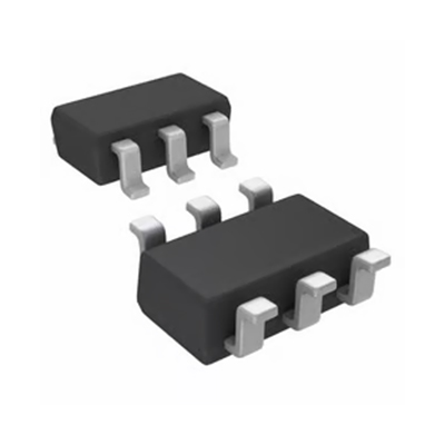
- Confirm six leads and pin-1 orientation against the Analog Devices top-view drawing.
- Place the input bypass capacitor close to IN and GND.
- Use the TSOT thermal model; do not apply TDFN exposed-pad assumptions.
The JPG is a generic package illustration. The package registry currently flags the TSOT-23-6 image as missing despite a reachable JPG, so visual approval remains pending.
Pin Functions
The following top-view pin assignment is specific to the six-lead TSOT variant.
Active-high enable; tie high or to IN for operation, pull low for shutdown.
Ground return.
Input supply; bypass to GND close to the pin.
Regulated output; connect the specified ceramic capacitor.
Open-drain power-good signal; pull up when used.
Feedback divider input for output adjustment.
The six-pin TDFN option uses a different pin arrangement and an exposed pad; it is not pin-for-pin interchangeable.
Key Specifications
| Manufacturer | Analog Devices / Maxim Integrated |
|---|---|
| Function | Adjustable linear regulator |
| Input voltage | 4 V to 60 V |
| Output setting | 0.6 V to 58 V, subject to headroom |
| Maximum output current | 100 mA, thermally limited |
| Feedback reference | 0.6 V nominal |
| No-load supply current | 8 µA typical |
| Shutdown current | 0.9 µA typical |
| Dropout at 100 mA | 560 mV typical at the specified test condition |
| Operating ambient temperature | -40 °C to +125 °C |
| Package | Six-lead TSOT, tape and reel |
Typical values and electrical limits apply only under data-sheet test conditions. Verify output capacitor selection and derating for the chosen output voltage.
Replacement Considerations
Compare the full ordering code, TSOT pinout, input and output range, PGOOD behavior, EN levels, output-current and thermal limits, capacitor requirements and assembly format before substitution. Similar six-lead packages do not establish electrical or footprint compatibility.
No internal substitute link is provided without an exact product-record and engineering comparison.
Manufacturer Information
Analog Devices lists MAX17651AZT+T in the MAX17651 data sheet ordering table as the six-lead TSOT tape-and-reel variant. The data sheet provides the controlled electrical, pin-function, package and thermal information used for design verification.
Applications
Small auxiliary rails from higher-voltage field supplies.
Low-load supply rails where standby current matters.
Monitored low-current regulation for metering electronics.
Linear filtering after a suitable switching supply.
Quality & Authenticity
Verify the complete MAX17651AZT+T ordering code, reel label, package marking, pin orientation and lot documentation against the manufacturer's current material. A generic package JPG is illustrative and cannot authenticate the delivered component.
FAQ
Is MAX17651AZT+T a fixed-output part?
No. Its output is set with an external feedback divider.
What is the maximum rated load?
100 mA, provided the actual voltage drop and TSOT thermal conditions permit it.
Does this option have an exposed pad?
No. The AZT ordering option is six-lead TSOT; the ATT TDFN option has an exposed pad.
What does PGOOD indicate?
It is an open-drain status output that changes state as feedback crosses the data-sheet thresholds.
Is the displayed image a certified footprint?
No. Use the manufacturer outline and land pattern for PCB layout.
Engineering Notice
Use the latest Analog Devices MAX17651 data sheet and package drawing for the feedback divider, input bypass, output capacitor, PGOOD pull-up and thermal design. The data sheet calls for at least 10 µF output capacitance below 1.8 V, or 4.7 µF at 1.8 V and above, in the specified ceramic size. Check capacitor effective capacitance under DC bias, dropout and dissipation over the full operating range.
MAX17651AZT+T Information
- Specifications
- Tags
- Product attributes
- Attribute value
- Manufacturer:
- Analog Devices Inc./Maxim Integrated
- Series:
- -
- Package/Case:
- SOT-23-6 Thin, TSOT-23-6
- Packaging:
- Tape & Reel (TR)
- Product Status:
- Active
- Output Configuration:
- Positive
- Output Type:
- Adjustable
- Number of Regulators:
- 1
- Voltage - Input (Max):
- 60V
- Voltage - Output (Min/Fixed):
- 0.6V
- Voltage - Output (Max):
- 58V
- Voltage Dropout (Max):
- 1.1V @ 100mA
- Current - Output:
- 100mA
- Current - Quiescent (Iq):
- 15 µA
- Current - Supply (Max):
- -
- PSRR:
- -
- Control Features:
- Enable, Power Good
- Protection Features:
- Over Current, Over Temperature, Short Circuit
- Operating Temperature:
- -40°C ~ 125°C (TA)
- Grade:
- -
- Qualification:
- -
- Mounting Type:
- Surface Mount
- Supplier Device Package:
- TSOT-23-6
- Include Parts
- Popular Search
The following parts include "MAX17651AZT+T" in Silicon Labs MAX17651AZT+T.
- Part Number
- Manufacturer
- Package
- Description
- MIC5504-1.8YM5-TR Microchip Technology SC-74A, SOT-753 IC REG LINEAR 1.8V 300MA SOT23-5
- MIC5504-3.3YM5-TR Microchip Technology SC-74A, SOT-753 IC REG LINEAR 3.3V 300MA SOT23-5
- MIC5365-3.0YC5-TR Microchip Technology 5-TSSOP, SC-70-5, SOT-353 IC REG LINEAR 3V 150MA SC70-5
- MIC5365-1.8YC5-TR Microchip Technology 5-TSSOP, SC-70-5, SOT-353 IC REG LINEAR 1.8V 150MA SC70-5
- MIC5365-2.5YC5-TR Microchip Technology 5-TSSOP, SC-70-5, SOT-353 IC REG LINEAR 2.5V 150MA SC70-5
- MIC5365-3.3YC5-TR Microchip Technology 5-TSSOP, SC-70-5, SOT-353 IC REG LINEAR 3.3V 150MA SC70-5
- MIC5365-3.3YD5-TR Microchip Technology SOT-23-5 Thin, TSOT-23-5 IC REG LIN 3.3V 150MA TSOT23-5
- MIC5317-3.3YM5-TR Microchip Technology SC-74A, SOT-753 IC REG LINEAR 3.3V 150MA SOT23-5
- TLV1117LV33DCYR Texas Instruments TO-261-4, TO-261AA IC REG LINEAR 3.3V 1A SOT223-4
- MIC5317-3.3YMT-TZ Microchip Technology 4-UDFN Exposed Pad IC REG LINEAR 3.3V 150MA 4DFN
The following parts are popular search parts in Test and Measurement.
Inventory:7,088
Please send an inquiry. Send us your inquiry, and we will respond immediately.


