 Hello! now
 tms@lcdchip.com



Analog Devices Inc./Maxim Integrated DS2413Q+T&R

- Part No.:
- DS2413Q+T&R
- Manufacturer:
- Analog Devices Inc./Maxim Integrated
- Category:
- Specialized ICs
- Package:
- 6-WDFN Exposed Pad
- Description:
- IC ADDRESSABLE SWITCH 6TDFN
- Quantity:
Unit Price:$0
Ext Price:$0
- Payment:

- Shipping:


Product Details
DS2413Q+T&R - 1-Wire Dual-Channel Addressable Switch
DS2413Q+T&R is an Analog Devices/Maxim dual-channel programmable 1-Wire I/O switch. Its two open-drain PIO channels can each sink up to 20 mA continuously, and the exact Q+T&R order code uses a six-pin exposed-pad TDFN supplied on tape and reel.
The 1-Wire bus supplies device power parasitically; system pullup, timing and output-state behavior must be validated with the actual load.
Overview
The DS2413 lets a 1-Wire master address two programmable open-drain I/O pins over a single serial connection. Dedicated PIO commands read both pin states and write their output latches; a factory-lasered, unique 64-bit ROM registration number supports addressing in a multidrop network. The device draws operating power from the 1-Wire line rather than a separate VCC pin.
Key Advantages
PIOA and PIOB can sense pin states or sink external loads.
1-Wire communication minimizes host interconnects and supports multidrop addressing.
The manufacturer specifies high-voltage PIO operation and a 28 V maximum continuous fault condition for IO.
A factory-lasered 64-bit ROM identifier distinguishes devices on one bus.
Feature Summary
Each PIO supports up to 20 mA continuous sink capability and up to 28 V off-state operating voltage.
PIO Access Write includes an inverted data byte and a confirmation/readback step.
Standard and overdrive 1-Wire modes support maximum stated rates of 14.9 kbps and 100 kbps.
The manufacturer specifies a 2.8 V to 5.25 V 1-Wire pullup operating range and 0°C to +70°C ambient.
Package & Footprint
LCDChip registers 6-WDFN Exposed Pad. Analog Devices lists DS2413Q+T&R as a six-pin TDFN with exposed paddle, package code T633+2, on tape and reel. The P+T&R alternative is TSOC, with different pin assignments and footprint.
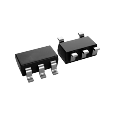
- Use the controlled six-pin TDFN outline and pin-one marking.
- Connect both ground pins and solder the exposed paddle to the ground plane.
- Size PIO load and 1-Wire pullup for the board's actual conditions.
The expected local JPG is absent and the production JPG URL returns HTTP 404. Keep this draft unpublished until the correct image is restored and inspected.
Pin Functions
For the Q-version TDFN, pin 1 is not connected; pin 2 is the open-drain 1-Wire IO requiring an external pullup; pin 3 is GND1; pin 4 is PIOA; pin 5 is GND2; and pin 6 is PIOB. Both ground pins must be connected. The exposed paddle is soldered to the board ground plane. The TSOC pin mapping is different and must not be applied to this Q order code.
Key Specifications
| Function | Dual-channel, addressable 1-Wire I/O switch |
|---|---|
| Exact order code | DS2413Q+T&R |
| Package | Six-pin exposed-pad TDFN, code T633+2 |
| Supply format | Tape and reel |
| Ambient temperature | 0°C to +70°C |
| 1-Wire pullup operating range | 2.8 V to 5.25 V |
| PIO channels | Two, open drain |
| Continuous PIO sink | 20 mA maximum per pin |
| PIO off-state voltage | 28 V maximum |
| PIO pulldown on-resistance | 20 Ω maximum |
| ROM identification | Unique 64-bit registration number |
| Standard bus rate | 14.9 kbps maximum |
| Overdrive bus rate | 100 kbps maximum |
Use the manufacturer's electrical and timing tables for design limits; absolute maximum fault ratings are not normal operating conditions.
Replacement Considerations
Other 1-Wire switches can differ in PIO command protocol, pullup and parasitic-power behavior, load ratings and ROM addressing. The DS2413P+T&R TSOC version uses a different footprint and pin mapping. Do not treat a six-pin package or 1-Wire label as proof of interchangeability. No unverified internal alternative is linked.
Manufacturer Information
Analog Devices' DS2413 1-Wire Dual-Channel Addressable Switch data sheet Rev. 5 (May 2022) supplies the exact Q+T&R ordering row, TDFN pin table, electrical ratings and PIO command behavior. Check the current controlled package drawing before board release.
Applications
Switch appropriately limited indicator loads from a remote 1-Wire node.
Address and control attached peripheral functions.
Read two remote I/O states through one bus contact.
Add simple addressed inputs and open-drain outputs to a supervised node.
Quality & Authenticity
Verify marking, traceability, TDFN dimensions and factory ROM ID. Test both PIO states, read-after-write confirmation, sink current, bus recovery and safe behavior if the 1-Wire connection is lost. Confirm exposed-paddle and ground connections on the production board.
FAQ
Does this device need a separate VCC pin?
No. The DS2413 is powered parasitically from its pulled-up 1-Wire IO.
Are the PIO outputs push-pull?
No. PIOA and PIOB are open-drain outputs.
Is Q+T&R the TSOC version?
No. Q+T&R specifies the exposed-pad TDFN supplied on tape and reel.
Why is this draft unpublished?
The registered package JPG is not available on the production site.
Engineering Notice
Confirm the latest data sheet, 1-Wire electrical timing, parasitic-power recovery, PIO load protection and TDFN land pattern before production. Restore and inspect the live package JPG before formal publication.
DS2413Q+T&R Information
- Specifications
- Tags
- Product attributes
- Attribute value
- Manufacturer:
- Analog Devices Inc./Maxim Integrated
- Series:
- -
- Package/Case:
- 6-WDFN Exposed Pad
- Packaging:
- Tape & Reel (TR)
- Product Status:
- Active
- Programmable:
- Not Verified
- Type:
- Addressable Switch
- Applications:
- Accessory ID and Control, Industrial Controllers, LED Control, System Monitoring
- Mounting Type:
- Surface Mount
- Supplier Device Package:
- 6-TDFN (3x3)
- Grade:
- -
- Qualification:
- -
- Include Parts
- Popular Search
The following parts include "DS2413Q+T&R" in Silicon Labs DS2413Q+T&R.
- Part Number
- Manufacturer
- Package
- Description
- CAP200DG-TL Power Integrations 8-SOIC (0.154", 3.90mm Width) IC AUTOMATIC DISCHARGE 8SO
- ATSHA204A-MAHDA-T Microchip Technology 8-UFDFN Exposed Pad IC AUTHENTICATION CHIP 8UDFN
- ATSHA204A-SSHDA-T Microchip Technology 8-SOIC (0.154", 3.90mm Width) IC AUTHENTICATION CHIP 8SOIC
- ATSHA204A-STUCZ-T Microchip Technology TO-236-3, SC-59, SOT-23-3 IC AUTHENTICATION CHIP SOT23-3
- ATECC608B-MAHDA-T Microchip Technology 8-UFDFN Exposed Pad IC AUTHENTICATION CHIP 8UDFN
- ATECC608B-MAHCZ-S Microchip Technology 8-UFDFN Exposed Pad IC AUTHENTICATION CHIP 8UDFN
- ATECC608B-SSHDA-T Microchip Technology 8-SOIC (0.154", 3.90mm Width) IC AUTHENTICATION CHIP 8SOIC
- ATECC608B-MAHDA-S Microchip Technology 8-UFDFN Exposed Pad IC AUTHENTICATION CHIP 8UDFN
- ATECC608A-MAHDA-S Microchip Technology 8-UFDFN Exposed Pad IC AUTHENTICATION CHIP 8UDFN
- ATECC608B-MAVDA-T Microchip Technology 8-UFDFN Exposed Pad IC AUTHENTICATION CHIP 8UDFN
The following parts are popular search parts in Test and Measurement.
Inventory:3,629
Please send an inquiry. Send us your inquiry, and we will respond immediately.


