 Hello! now
 tms@lcdchip.com



Analog Devices Inc./Maxim Integrated MAX4506ESA+T
- Part No.:
- MAX4506ESA+T
- Manufacturer:
- Analog Devices Inc./Maxim Integrated
- Category:
- Specialized ICs
- Package:
- 8-SOIC (0.154", 3.90mm Width)
- Description:
- IC OVERVOLTAGE PROTECTION 8SOIC
- Quantity:
Unit Price:$0
Ext Price:$0
- Payment:

- Shipping:


Product Details
MAX4506ESA+T - Triple Fault-Protected Signal-Line Protector
MAX4506ESA+T is a Maxim Integrated, now Analog Devices, three-channel fault-protected analog signal-line protector. Analog Devices lists the exact MAX4506ESA+T model in its 8-pin narrow SOIC product table; the ESA temperature grade is -40 C to +85 C. It is intended to shield downstream signal circuitry from input overvoltage.
The three protection paths are always enabled when powered; this is not a logic-controlled analog multiplexer.
Overview
The MAX4506 places three independent fault-protected paths between analog inputs and outputs. Signals within the supply rails pass through, while a fault on an input causes its output to clamp toward the appropriate supply rail. The paths open when power is removed. Designs may use unipolar or bipolar supplies within the manufacturer's operating ranges.
Key Advantages
A fault on one channel does not force the other on-channels to the fault level.
The input fault-protection range extends to ±40 V with supplies off.
Input fault protection extends to ±36 V with the device powered.
Protection paths are always on when supplies are present, with no digital enable pins.
Feature Summary
Rail-to-rail analog signal passage within the operating supply range.
The data sheet lists 10 ns overvoltage turn-on delay and output rail clamping.
100 ohms maximum, with channel matching specified in the manufacturer data sheet.
The ESA grade is industrial-temperature; Analog Devices lists this exact plus-T model in the 8-pin narrow-SOIC package.
Package & Footprint
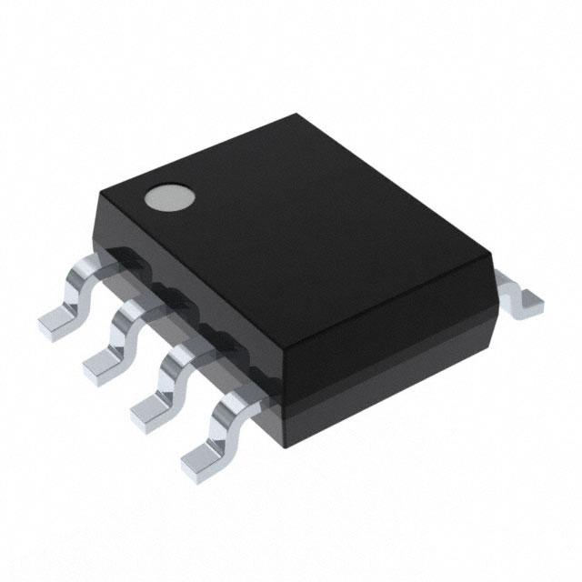
Maxim's data-sheet ordering table specifies the ESA temperature/package family as 8-pin SO, -40 C to +85 C; Analog Devices lists the exact MAX4506ESA+T model as narrow SOIC. The package is the narrow 0.150-inch SOIC class; LCDChip registers it as 8-SOIC (0.154", 3.90 mm width). Verify the controlled outline, land pattern and pin-one mark for board release.

- Keep fault-facing IN traces separated from protected OUT nodes.
- Confirm V+ and V- supply routing and decoupling.
- Check pin-one orientation against the manufacturer drawing.
This generic JPG does not show device-specific pins.
Pin Functions
The MAX4506 SO/DIP top-view diagram assigns pins 1, 2 and 3 to IN1, IN2 and IN3; pin 4 to V-; pins 5, 6 and 7 to OUT3, OUT2 and OUT1; and pin 8 to V+. Each numbered IN/OUT pair forms one protection path. Confirm the top-view orientation and supply polarity before routing.
Key Specifications
| Function | Fault-protected analog signal-line protector |
|---|---|
| Channels | Three independent always-on paths |
| Industrial temperature | -40 C to +85 C |
| Unipolar supply | +9 V to +36 V |
| Bipolar supplies | ±8 V to ±18 V |
| Powered input protection | ±36 V |
| Power-off input protection | ±40 V |
| On resistance | 100 ohms maximum |
| Overvoltage response | 10 ns data-sheet-listed turn-on delay |
| Logic control pins | None |
| Package | 8-pin narrow SOIC |
Protection ranges and electrical limits have conditions; consult the controlled data sheet for current, timing and test details.
Replacement Considerations
A same-size SOIC or newer plus-suffixed order code is not automatically interchangeable. Confirm three-channel pinout, supply topology, protected fault range, output clamp current, on-resistance, temperature grade, package materials and lifecycle. No unverified internal alternative link is asserted.
Manufacturer Information
Maxim Integrated's MAX4506/MAX4507 Fault-Protected, High-Voltage Signal-Line Protectors data sheet, 19-1415 Rev 2, documents the ESA temperature/package family, SO/DIP pin configuration, fault behavior and electrical characteristics. Analog Devices hosts the manufacturer data sheet and lists the exact MAX4506ESA+T orderable model.
Applications
Protect measurement front ends from out-of-range analog inputs.
Isolate sensitive controller inputs from field-wiring faults.
Limit signal-line disturbances during board insertion or removal.
Add fault-tolerant input paths to instrumentation channels.
Quality & Authenticity
Verify the complete MAX4506ESA+T order code, 8-pin narrow SOIC package, markings, lot label and traceability. Incoming electrical checks should cover path continuity under nominal conditions and appropriate fault isolation under controlled test limits.
FAQ
How many paths does MAX4506ESA+T protect?
Three independent analog signal paths.
What does the ESA grade specify?
The industrial -40 C to +85 C grade in an 8-pin SOIC package; the exact plus-T model is listed on the Analog Devices product page.
Does it require a logic enable signal?
No. Paths are always on when the supplies are present.
Can it protect an unpowered board?
The manufacturer specifies input fault protection to ±40 V with supplies off, subject to its data-sheet conditions.
Engineering Notice
Use the current Analog Devices-hosted MAX4506/MAX4507 data sheet, package drawing and applicable notices for final design approval. Verify power sequencing, fault current, protected-device ratings and thermal limits; the presence of a protector does not remove system-level surge and safety requirements.
MAX4506ESA+T Information
- Specifications
- Tags
- Product attributes
- Attribute value
- Manufacturer:
- Analog Devices Inc./Maxim Integrated
- Series:
- -
- Package/Case:
- 8-SOIC (0.154", 3.90mm Width)
- Packaging:
- Tape & Reel (TR)
- Product Status:
- Active
- Programmable:
- Not Verified
- Type:
- Overvoltage Protection
- Applications:
- Control Systems
- Mounting Type:
- Surface Mount
- Supplier Device Package:
- 8-SOIC
- Grade:
- -
- Qualification:
- -
- Include Parts
- Popular Search
The following parts include "MAX4506ESA+T" in Silicon Labs MAX4506ESA+T.
- Part Number
- Manufacturer
- Package
- Description
- CAP200DG-TL Power Integrations 8-SOIC (0.154", 3.90mm Width) IC AUTOMATIC DISCHARGE 8SO
- ATSHA204A-MAHDA-T Microchip Technology 8-UFDFN Exposed Pad IC AUTHENTICATION CHIP 8UDFN
- ATSHA204A-SSHDA-T Microchip Technology 8-SOIC (0.154", 3.90mm Width) IC AUTHENTICATION CHIP 8SOIC
- ATSHA204A-STUCZ-T Microchip Technology TO-236-3, SC-59, SOT-23-3 IC AUTHENTICATION CHIP SOT23-3
- ATECC608B-MAHDA-T Microchip Technology 8-UFDFN Exposed Pad IC AUTHENTICATION CHIP 8UDFN
- ATECC608B-MAHCZ-S Microchip Technology 8-UFDFN Exposed Pad IC AUTHENTICATION CHIP 8UDFN
- ATECC608B-SSHDA-T Microchip Technology 8-SOIC (0.154", 3.90mm Width) IC AUTHENTICATION CHIP 8SOIC
- ATECC608B-MAHDA-S Microchip Technology 8-UFDFN Exposed Pad IC AUTHENTICATION CHIP 8UDFN
- ATECC608A-MAHDA-S Microchip Technology 8-UFDFN Exposed Pad IC AUTHENTICATION CHIP 8UDFN
- ATECC608B-MAVDA-T Microchip Technology 8-UFDFN Exposed Pad IC AUTHENTICATION CHIP 8UDFN
The following parts are popular search parts in Test and Measurement.
Inventory:1,293
Please send an inquiry. Send us your inquiry, and we will respond immediately.


