Hello! now
 tms@lcdchip.com


Mitsubishi Q Series Ethernet Communication, Troubleshooting and Spare Parts Guide
The QJ71E71-100 Ethernet module is a small part of a Mitsubishi Q Series PLC rack, but when communication fails, it can stop HMI operation, SCADA data collection, recipe transfer, remote monitoring, production reporting and maintenance access. The difficult part is that the module itself is not always the failed component.
A QJ71E71-100 communication error can come from the PLC CPU, HMI project, IP address, subnet, open settings, TCP/UDP configuration, fixed buffer setup, Ethernet cable, switch port, duplicate address, routing, station settings or an actual hardware fault. This guide gives maintenance engineers and sourcing teams a practical way to narrow the cause before replacing the module.
Why QJ71E71-100 Faults Are Often Misdiagnosed
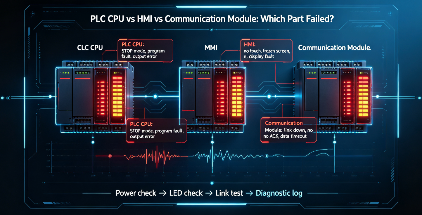
A communication alarm on the HMI does not prove that the QJ71E71-100 module has failed. It only means that one device in the communication path cannot exchange data as expected. The Ethernet module is one part of that path. The actual fault may be in the HMI project, PLC CPU status, cable, network switch, IP settings, connection configuration or the device trying to communicate with the PLC.
The safest approach is to separate the system into layers and test each layer in order. If the physical link is down, open settings do not matter yet. If the PLC CPU is in STOP or ERROR state, an HMI may report communication failure even though the Ethernet module is electrically healthy.
PLC rack power, CPU condition, module seating and slot assignment.
RJ45 connector, cable quality, switch port, speed negotiation and link LED.
IP address, subnet mask, gateway, duplicate IP and network segment.
TCP, UDP, port number, open setting and connection count.
Device memory, buffer, PLC program, protocol and access range.
HMI, SCADA, OPC server, PC tool, robot, gateway or data logger.
Common Symptoms and What They Usually Mean
| Symptom | Likely Fault Area | First Checks |
|---|---|---|
| HMI shows PLC communication error | HMI project, Ethernet settings, cable, PLC CPU, QJ71E71-100 | Check PLC RUN status, module LEDs, HMI driver, IP and port settings |
| No link LED on QJ71E71-100 | Cable, switch port, RJ45 connector, module hardware | Try known-good cable and known-good switch port before replacing module |
| Engineering PC can ping module but HMI cannot connect | HMI driver, port, protocol, open setting, device address | Compare ping result with actual PLC data communication settings |
| SCADA reads data intermittently | Network load, connection count, polling rate, switch, cable, PLC scan timing | Reduce polling load, check error timing and compare with production events |
| Connection works after power cycle then fails again | Duplicate IP, unstable switch, thermal issue, connection leak, client reconnect logic | Check IP conflict, switch logs, cabinet temperature and client behavior |
| Replacement module powers on but still cannot communicate | Missing parameters, wrong slot, wrong open settings, wrong IP, no project backup | Restore module parameters and compare rack configuration |
| Only one external device cannot connect | Client-side configuration, protocol mismatch, port, firewall or route | Check whether other devices can communicate with the same PLC |
| All Ethernet devices lose communication at once | Switch, power supply, cabinet network, PLC CPU state or module failure | Check network switch power, PLC CPU status and link LEDs together |
Start with the Physical Link
It is tempting to open software first, but the physical layer should be checked before spending time on parameters. A damaged RJ45 plug, poor cabinet cable, failed switch port or missing switch power can produce the same visible symptom as a configuration problem.
Physical Link Checklist
- Check whether the Ethernet link LED is on at both module and switch.
- Replace the cable with a known-good short cable for testing.
- Move the cable to a known-good switch port.
- Check whether the cabinet switch is powered from the same 24VDC circuit as other failed devices.
- Inspect RJ45 plug locking tab, bent contacts and corrosion.
- Check whether the cable is routed near high-noise motor, inverter or power wiring.
- Check whether communication fails when the cabinet door moves or vibration occurs.
- Confirm cable length and quality are appropriate for the installation.
If the link LED never appears with a known-good cable and switch port, then the module port, switch, or client-side port should be investigated. Do not change PLC parameters until the physical link is stable.
Ping Is Useful, But It Does Not Prove PLC Communication Works
A successful ping only confirms that a device responds at the IP layer. It does not prove that the HMI driver, SCADA protocol, TCP open setting, fixed buffer, port number, device address or PLC program access is correct.
The PC can reach the Ethernet module address.
Application must match port, open setting, data area and request method.
When Ping Works but Communication Fails
- The HMI or SCADA uses the wrong PLC driver.
- The port number does not match the module open setting.
- TCP is configured on one side while UDP is expected on the other.
- The open setting was not downloaded after module replacement.
- The client requests a device area or address range not supported by the project.
- The connection count is already used by other clients.
- Network routing allows ping but blocks application-level communication.
- PLC CPU is not in the expected operating state.
IP Address, Subnet and Duplicate Address Checks
Many QJ71E71-100 problems are not hardware failures. They are ordinary network problems inside a control cabinet. A duplicate IP address can create intermittent faults that seem random. A wrong subnet can allow local testing from one laptop but fail from the HMI or SCADA station.
Confirm the module address matches drawings, HMI project and SCADA configuration.
Confirm the HMI, PLC and SCADA are in the expected network segment.
Check only if traffic crosses network segments or routed industrial network zones.
Disconnect suspected duplicate devices or scan the network carefully.
Ask whether IT, maintenance or OEM staff changed switch, router or HMI settings.
Compare current network values with drawings, screenshots and project files.
Duplicate IP Clues
- Communication works after reboot but fails again later.
- Ping response time changes unexpectedly.
- The HMI connects sometimes, while SCADA or a PC disconnects.
- A new device was added to the cabinet or plant network recently.
- Only one client can communicate reliably at a time.
- Switch MAC address table or network scan shows inconsistent mapping.
Open Settings: The Part People Often Forget After Replacement
The QJ71E71-100 is not only an Ethernet port. It must be configured for the intended communication method. After a module replacement, a physical swap may not restore operation unless the same IP address, open settings and related parameters are restored.
Open Setting Troubleshooting Questions
- Was the module recently replaced?
- Was the PLC parameter file downloaded after replacement?
- Does the HMI or SCADA use TCP or UDP?
- Does the client connect to the correct port number?
- Is the module configured as expected for passive or active connection behavior?
- Does the PLC program use fixed buffer communication?
- Are there enough open connections for all clients?
- Does engineering software occupy a connection during testing?
Connection Count and Polling Load
Intermittent communication may appear when too many devices poll the PLC too aggressively. A typical line may have one GOT HMI, one SCADA server, one engineering laptop, one data collector and one gateway. Each device may be harmless alone, but together they can create timing and connection-management problems.
Polling and Load Checks
- Check how many clients connect to the module at the same time.
- Reduce SCADA or OPC polling rate during troubleshooting.
- Temporarily disconnect nonessential clients.
- Check whether communication fails during shift start, recipe download or reporting upload.
- Check whether engineering software is connected while the HMI and SCADA are also active.
- Review whether new data-collection software was added recently.
- Group data reads efficiently rather than polling many scattered addresses.
TCP vs UDP: Check Both Sides
When one side expects TCP and the other side is configured for UDP, communication will fail even if the Ethernet link and IP address are correct. The same problem happens when the port number or connection role differs from the client configuration.
Common when the client expects a session-style connection and confirmed stream behavior.
Used in some application-specific communication methods where packets are exchanged without a persistent session.
The external device must use the port number configured in the module parameters.
Confirm whether the PLC side waits for a connection or initiates one.
Protocol Mismatch Clues
- Ping succeeds, but application connection always times out.
- One SCADA driver works while another fails.
- Communication fails only after project download or module replacement.
- The external device log shows connection refused or no response.
- The HMI uses a different Mitsubishi driver than the original project.
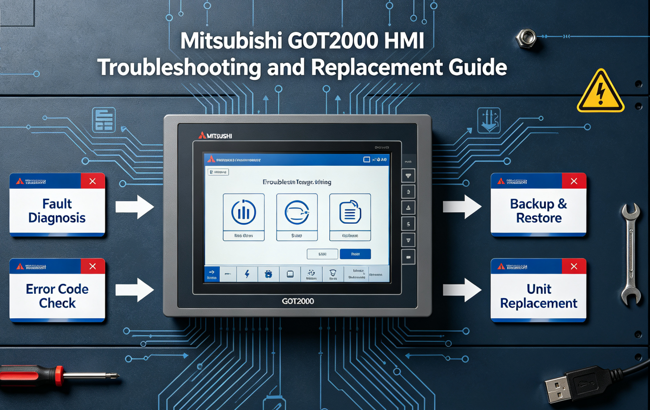
HMI Cannot Connect to QJ71E71-100
When a GOT or third-party HMI cannot connect to the PLC through QJ71E71-100, check the HMI project and the Ethernet module together. The HMI screen may show a simple communication alarm, but the root cause may be very specific.
Confirm the selected PLC series and Ethernet communication driver.
Confirm the HMI points to the correct Ethernet module address and port.
Confirm the requested D, M, X, Y or other device areas are valid.
Check whether the HMI connects directly or through another network device.
Check whether a screen update changed communication settings.
Confirm the CPU state before blaming the HMI or Ethernet module.
HMI-Side Checks
- Confirm the HMI project is the correct machine version.
- Compare HMI communication settings with a backup or old screenshot.
- Check whether the HMI can communicate with another known-good PLC.
- Check whether the PLC can be reached from an engineering PC through the same switch.
- Confirm whether the HMI and PLC are on the same subnet.
- Check whether the HMI was replaced and downloaded with a default project.
SCADA, OPC or Data Logger Cannot Read PLC Data
SCADA and data-collection faults are usually more subtle than HMI faults. The machine may still operate, but production data, alarms or historian records stop updating. In this situation, do not replace the Ethernet module before reviewing the client driver and polling behavior.
SCADA Troubleshooting Checklist
- Check whether the SCADA driver supports the exact Mitsubishi communication method used.
- Confirm tag addresses and data types.
- Reduce polling rate and test a small group of tags.
- Check whether the problem affects all tags or only one data block.
- Review whether a firewall, VPN, VLAN or router was changed.
- Confirm whether the PLC CPU is in RUN and updating the requested data.
- Check whether another client already uses the expected connection.
- Compare current SCADA settings with the last known working backup.
When to Suspect Hardware Failure
After physical link, IP settings, open settings, client configuration and PLC status are checked, the module itself may become the likely suspect. Hardware failure is more likely when symptoms remain consistent across known-good cables, known-good switch ports and restored parameters.
Module port may be damaged if the switch and cable are proven good.
LED status remains abnormal after power cycle and parameter verification.
Rack configuration or PLC diagnostics indicate module recognition fault.
Communication drops with vibration, heat or connector movement.
Burn marks, liquid exposure, broken RJ45 jack or corrosion are visible.
A tested replacement works in the same slot with the same cable and parameters.
If a module is suspected to be damaged by surge, grounding fault or cabinet contamination, check the root cause before installing another unit. Otherwise the replacement module may fail again.
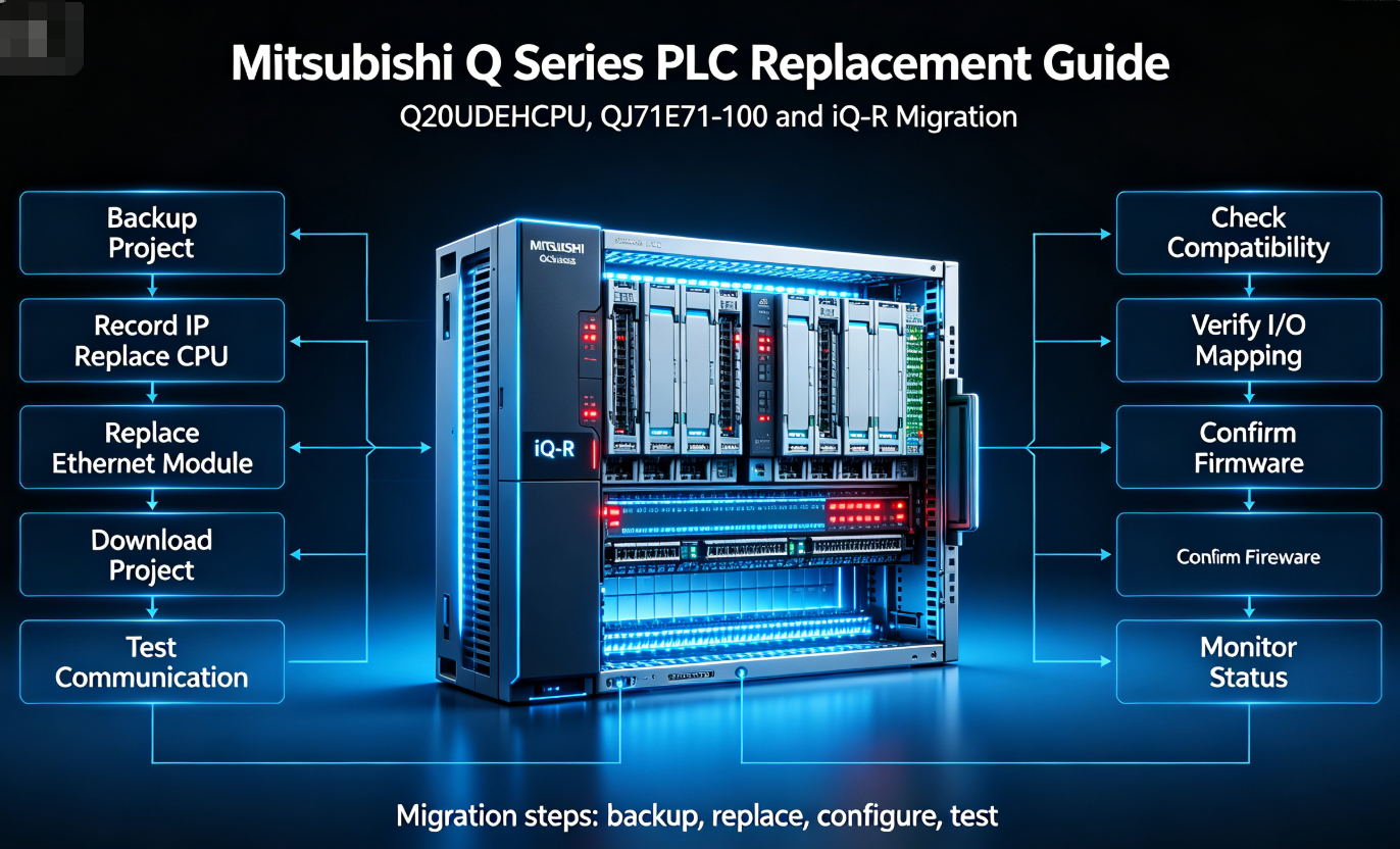
Replacement Checklist for QJ71E71-100
Replacing QJ71E71-100 should be treated as a controlled maintenance task. Record the old module, backup the project, verify parameters and validate communication after installation.
Photograph module label, slot position, wiring and switch connection.
Save PLC program, parameters, IP settings and HMI/SCADA configuration.
Install the verified module in the same slot and reconnect the cable.
Download or confirm Ethernet module parameters and open settings.
Test HMI, SCADA, engineering PC, alarms, data exchange and machine sequence.
Before Buying a Replacement Module
- Confirm the exact model is QJ71E71-100.
- Photograph the current module label and rack slot.
- Confirm whether the module is connected to HMI, SCADA, OPC, gateway or robot.
- Check whether Ethernet parameters are available in the PLC project.
- Confirm whether a same-model spare is required urgently.
- Ask whether the offered part is new, surplus, used or refurbished.
- Request real photos of the exact unit.
- Request test evidence if the unit is not factory sealed.
- Confirm warranty and return conditions before shipment.
What Test Evidence Should a Supplier Provide?
For an Ethernet module, a useful test is not only a photo of the front label. The buyer should ask for evidence that the module powers on, is recognized, and can perform the communication function relevant to the repair situation.
Field Case: HMI Alarm After QJ71E71-100 Replacement
A common field situation is straightforward: the old module was replaced, link LEDs appear normal, but the HMI still shows communication error. In many cases, the replacement module is not the issue. The missing step is parameter restoration.
What to Do
- Compare old and new module IP settings.
- Restore PLC parameters from the known-good project.
- Confirm open settings and port numbers.
- Confirm HMI driver and target address.
- Power cycle according to the maintenance procedure if required.
- Test with engineering PC, HMI and SCADA separately.
Recommended LcdChip Parts and Related Content
QJ71E71-100 is often sourced together with Q Series CPUs, GOT HMI panels and migration-related parts. If communication faults appear on an older production line, record the full system instead of asking for only one module.
QJ71E71-100
Mitsubishi Q Series Ethernet interface module used for HMI, SCADA, engineering PC, gateway and plant network communication.
Search QJ71E71-100Q20UDEHCPU
MELSEC-Q CPU module commonly reviewed together with Ethernet communication faults, program backup and spare-parts planning.
View Q20UDEHCPUGT2715-XTBA
Mitsubishi GOT HMI panel used for operator screens, alarms, recipes and PLC data display through Ethernet or serial communication.
View GT2715-XTBA GuideR32CPU
iQ-R CPU considered when a factory plans long-term migration from aging Q Series systems instead of only emergency same-model replacement.
Search R32CPUHow to Prepare a QJ71E71-100 RFQ
A good RFQ should help the supplier confirm the exact part and understand the communication problem. If the machine is stopped, include photos and symptoms rather than only a model number.
Recommended RFQ Information
- Exact model number: QJ71E71-100
- Photo of the module label and front LEDs
- PLC CPU model and rack photo
- Slot position of the Ethernet module
- Connected devices: HMI, SCADA, OPC, robot, gateway or PC
- Fault symptom: no link, HMI error, SCADA timeout, intermittent disconnect or no data
- Current LED status
- Whether ping works
- Whether engineering software can go online
- Whether IP and open settings are available from the PLC project
- Whether the machine is stopped or this is a preventive spare purchase
- Required condition: new, surplus, used, refurbished or tested working
- Delivery country and urgency
- Warranty or return requirement
Need Help with QJ71E71-100 Communication Error or Replacement?
Send the QJ71E71-100 label photo, LED status, PLC CPU model, HMI/SCADA connection details, IP setting status and machine urgency. LcdChip can help review Mitsubishi Q Series Ethernet modules, PLC CPUs, GOT HMI panels and related industrial automation spare parts.
Search QJ71E71-100 View Industrial Automation Parts Submit RFQFAQ: QJ71E71-100 Communication Error Troubleshooting
Why does my HMI show a communication error with QJ71E71-100?
The cause may be the HMI project, PLC CPU state, Ethernet cable, switch, IP address, open settings, port number, protocol mismatch or the QJ71E71-100 module itself. Check the full communication path before replacing hardware.
Does a successful ping prove QJ71E71-100 is working?
No. Ping only confirms IP reachability. PLC data communication still depends on protocol, port number, open settings, driver configuration and the client application.
What should I check first when QJ71E71-100 has no link?
Check the Ethernet cable, RJ45 connector, switch power, switch port and link LEDs. Use a known-good cable and switch port before assuming the module is defective.
Can QJ71E71-100 fail intermittently?
Yes, but intermittent communication may also come from duplicate IP address, bad cable, unstable switch, cabinet heat, polling overload, client reconnect behavior or loose connectors.
Why does communication still fail after replacing QJ71E71-100?
The replacement module may not have the correct IP settings, open settings, port configuration or PLC parameters. Restore the known-good project and validate HMI or SCADA communication.
What is the difference between a network problem and module failure?
A network problem usually changes when the cable, switch port, IP address or client device is changed. Module failure remains after known-good cable, switch, settings and client tests have been verified.
Should I keep a spare QJ71E71-100 module?
Yes, if the machine depends on Ethernet communication for HMI, SCADA, data collection or remote maintenance. A spare should be tested and stored with backup parameters.
What information should I send when buying QJ71E71-100?
Send the module label photo, rack photo, PLC CPU model, LED status, fault symptom, connected devices, backup status, required condition, delivery urgency and warranty requirement.