Hello! now
 tms@lcdchip.com


Industrial Automation Troubleshooting, Spare Parts and Machine Recovery Guide
When a production machine stops, the first question is usually simple: which part failed? The answer is rarely simple. A frozen HMI screen can be caused by the operator panel, the PLC CPU, a communication module, an Ethernet switch, a serial cable, a power supply, a lost program, incorrect parameters or even a machine interlock.
This guide gives maintenance engineers, automation buyers and sourcing teams a practical method for separating PLC CPU faults, HMI faults, communication-module faults, I/O faults, power problems and software or parameter issues before buying replacement parts.
Why This Diagnosis Matters Before Buying Spare Parts
Industrial automation replacement parts are often expensive, urgent and difficult to source. Buying the wrong part can extend downtime, create new compatibility problems and waste the remaining repair window. A PLC CPU, HMI panel and communication module may be connected in the same fault chain, but only one of them may actually be defective.
A structured diagnosis helps answer three practical questions: which device is failing, which replacement part is needed, and which software backup or parameter file is required before the machine can restart.
The HMI shows an alarm, but the real fault may be the PLC, network module, power supply or field device.
A replacement PLC CPU or HMI may power on but cannot run the machine without the correct program.
Similar model names may have different power, ports, memory, firmware or communication support.
A network switch, cable, station number or IP conflict may imitate a failed module.
Unverified touch input, outputs or machine state may create safety risk during restart.
Urgency often causes teams to order first and verify later, increasing sourcing mistakes.
First Rule: Separate the Control System into Blocks
A machine control system should be diagnosed as connected blocks, not as one black box. The PLC CPU executes logic. The HMI displays status and sends operator commands. Communication modules move data between devices. I/O modules connect the PLC to sensors and actuators. Power supplies keep every block alive. Software and parameters define how the hardware behaves.
The visible symptom may appear at one layer, while the root cause sits in another layer. For example, "HMI cannot communicate" may be caused by a PLC CPU in STOP mode, a failed Ethernet module, a wrong IP address, a damaged cable or a downloaded HMI project with incorrect driver settings.
Quick Symptom-to-Fault Table
| Machine Symptom | Most Likely Fault Area | First Checks |
|---|---|---|
| HMI is black and no power light appears | HMI power, cabinet power, fuse, terminal wiring | Measure HMI input voltage, check terminal block and cabinet power |
| HMI is on but shows communication error | PLC CPU state, Ethernet/serial module, cable, IP or protocol setting | Check PLC RUN state, link LEDs, cable and HMI communication settings |
| PLC CPU has ERROR LED | CPU diagnostic fault, program issue, module mismatch, battery or memory | Read PLC diagnostics with engineering software and check module configuration |
| PLC CPU is in STOP mode | Program error, manual STOP, safety condition, CPU fault | Check mode switch, software status, error code and recent maintenance changes |
| Only one remote rack or network area is offline | Communication module, network cable, remote power, node setting | Check module LEDs, network switch, node address and local power |
| One output device does not move | I/O module, field wiring, relay, fuse, actuator or interlock | Check PLC output status, terminal voltage and device-side power |
| Touch screen does not respond but display is normal | HMI touch panel, surface damage, calibration, project or freeze | Check whether all areas fail, clean screen and test project response |
| PLC can be reached from laptop but HMI cannot connect | HMI project setting, route, port, driver, IP conflict or network segment | Compare engineering software access with HMI communication configuration |
| Machine starts after power cycle but fails again later | Power instability, thermal fault, memory issue, aging module or loose wiring | Monitor temperature, voltage, cabinet fan, module seating and event timing |
| Replacement module powers on but machine still does not run | Missing program, wrong parameters, wrong model variant, incompatible firmware | Restore backup, compare configuration and validate with real machine sequence |
Diagnostic Step 1: Check Power Before Replacing Logic Modules
Many control faults begin with weak or missing power. A PLC rack may have internal power, while 24VDC field power is missing. An HMI may be powered but the Ethernet switch is off. A remote I/O station may be offline because a cabinet fuse is open.
Power Checks
- Measure input voltage at the device terminal, not only at the power supply output.
- Check voltage under load while the machine is attempting to start.
- Check rack power supply status LEDs.
- Check 24VDC distribution fuses and terminal blocks.
- Check cabinet fan, heat, moisture and contamination.
- Confirm the HMI, network switch and PLC are powered from the expected supply.
- Check for intermittent voltage drop during motor, heater or solenoid operation.
- Inspect loose terminal screws, damaged connectors and burnt wiring marks.
If several unrelated devices fail at the same time, suspect power or network infrastructure before ordering multiple replacement modules.
Diagnostic Step 2: Decide Whether the PLC CPU Is Healthy
The PLC CPU is the control brain of the machine. A real CPU fault can stop logic execution, disable communication and prevent outputs from operating. But the CPU is not always the cause just because the HMI displays a PLC error.
CPU Fault Indicators
- CPU remains in STOP mode and cannot be returned to RUN.
- ERROR LED remains active after reset.
- Engineering software reports CPU diagnostics or module mismatch.
- Program or memory cannot be read or written.
- Battery or memory-card fault appears.
- Communication with all devices fails, including direct programming connection.
- CPU becomes abnormally hot or resets repeatedly.
What to Check Before Buying a PLC CPU
- Exact CPU model and suffix.
- Rack, base unit and installed module configuration.
- Current error code or diagnostic message.
- Program backup status and programming software version.
- Memory card, battery and parameter files.
- Connected network modules and HMI communication method.
- Whether a same-model spare has been tested before.
- Whether a successor CPU requires migration instead of direct replacement.
Do Not Replace a PLC CPU Without Backup Planning
A blank replacement CPU may be physically correct but functionally useless without the correct PLC program, parameters, network settings and module configuration.
Diagnostic Step 3: Decide Whether the HMI Is the Failed Device
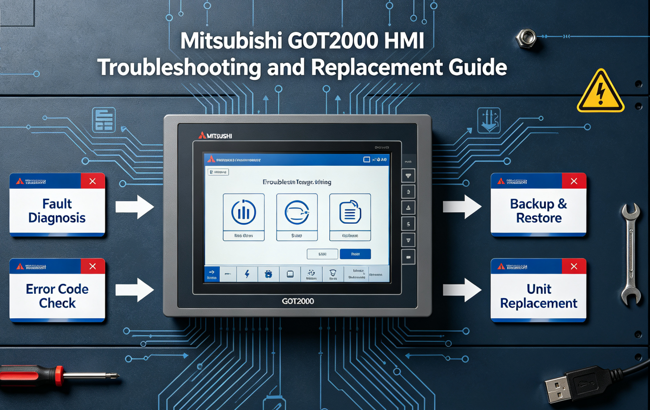
The HMI is the operator window into the control system. It may display alarms, send commands, store recipes and show production data. When it fails, the PLC may continue running, but operators may lose visibility and control.
Check HMI power, backlight, LCD, brightness setting and boot behavior.
Check touch panel wear, contamination, local dead zones and cabinet pressure.
Check project file, recipe, alarm history, fonts and communication driver.
Check HMI driver, IP address, station number, serial parameters and cable.
Signs the HMI May Be Faulty
- PLC runs normally, but HMI is black, white, frozen or unresponsive.
- Other systems can communicate with the PLC, but the HMI cannot.
- Touch fails in one area or generates random inputs.
- The HMI repeatedly restarts while PLC operation remains stable.
- USB or SD project transfer fails on the HMI.
- Backlight is dim, flickering or uneven.
- Communication settings changed after an HMI project download.
What to Check Before Buying an HMI Replacement
- Exact HMI model, power type and screen size.
- Panel cutout and mounting accessories.
- Communication ports used by the machine.
- Project backup and password status.
- Recipe, alarm and data-log requirements.
- Touch panel condition and front-panel environment.
- Firmware compatibility with the HMI project.
- Whether the replacement must be same model or can be upgraded.
Diagnostic Step 4: Decide Whether the Communication Module Failed
Communication modules are often blamed when the HMI cannot talk to the PLC, but the real cause may be a cable, switch, network address, route setting, serial parameter, project driver or PLC state. Treat the communication path as a full chain.
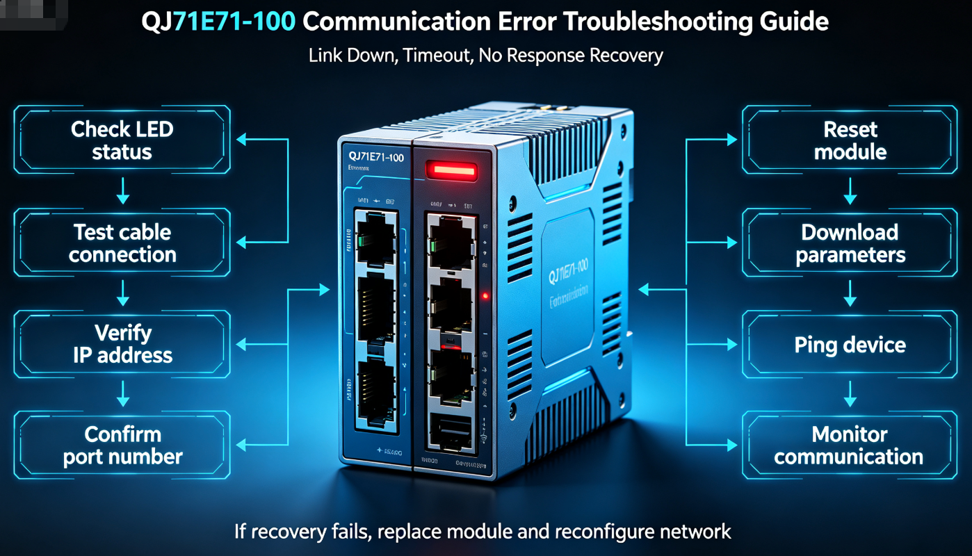
Ethernet Module Checks
- Check link LEDs on both module and switch.
- Confirm IP address, subnet mask and gateway.
- Check for duplicate IP address.
- Test cable and switch port with a known-good device.
- Ping the PLC-side device where permitted by the system.
- Check whether engineering software can go online with the PLC.
- Compare HMI project settings with actual PLC network settings.
- Check whether network routing or firewall rules changed.
- Read module diagnostics if supported.
Serial Communication Checks
- Confirm RS-232, RS-422 or RS-485 wiring type.
- Check connector pinout and shield grounding.
- Confirm baud rate, parity, data bits and stop bits.
- Confirm station number, node address or device ID.
- Check termination and biasing for RS-485 networks.
- Inspect loose screws, corrosion and damaged terminals.
- Compare HMI driver settings with PLC communication parameters.
If a laptop can go online with the PLC through the same network path, the communication module may be healthy. The remaining fault may be in HMI settings, protocol selection, routing, port configuration or application logic.
Diagnostic Step 5: Do Not Ignore I/O Modules and Field Devices
A machine fault that appears to be a PLC or HMI problem may actually be caused by a sensor, actuator, terminal block, relay, fuse, solenoid, drive or safety circuit. The PLC may be doing exactly what the program commands based on the input conditions it receives.
I/O Fault Clues
- PLC CPU is in RUN mode with no CPU error.
- HMI displays normal screens and communicates with PLC.
- Only one sensor, actuator, station or machine section is abnormal.
- PLC input status does not change when the physical sensor changes.
- PLC output status turns on, but no voltage reaches the field device.
- Manual output test works, but automatic sequence does not.
- Fault follows a field cable, terminal or device rather than the PLC rack.
Software and Parameter Problems Can Look Like Hardware Failures
After a download, replacement, battery loss or maintenance operation, a machine may fail because software or parameters are wrong rather than because hardware is defective. PLC programs, HMI projects, servo parameters, communication settings and memory data are part of the control system.
Signs the Fault May Be Software-Related
- The problem started immediately after a project or program download.
- A replacement module powers on but does not behave like the original.
- Communication fails after an IP address or station setting change.
- PLC diagnostics report a module configuration mismatch.
- HMI screens appear but tags show missing or invalid data.
- A servo drive is powered but parameters are missing or incorrect.
- The system works with an older backup but fails with the new project.
Decision Tree: Which Part Should You Suspect First?
Isolation Tests: Change One Variable at a Time
In emergency maintenance, teams often replace the HMI, communication cable and PLC module at the same time. This may restart the machine, but it prevents root-cause identification. When possible, isolate one variable at a time.
If the fault disappears, the cable or connector was likely the problem.
If PLC communication returns, the original HMI or project settings are suspect.
If communication returns, the switch port, converter or network path is suspect.
If the machine works with an older backup, the new program or parameters are suspect.
If one channel group recovers, the module or terminal block is suspect.
If intermittent resets stop, the original power source or wiring may be weak.
Example 1: HMI Shows "PLC Communication Error"
This is one of the most common factory symptoms. The HMI is alive, but it cannot read or write PLC data. Do not assume the HMI is bad immediately.
Likely Root Causes
- PLC is in STOP or ERROR state.
- Ethernet cable or switch port failed.
- HMI project uses the wrong PLC type or protocol.
- IP address, subnet or station number is incorrect.
- Communication module lost configuration or failed.
- CPU or communication module was replaced without restoring parameters.
- HMI project was downloaded with different tag or device settings.
Example 2: PLC CPU Error LED Is On
A CPU error should be read using engineering software whenever possible. The error code matters more than the general observation that the LED is on.
Logic, parameter or configuration issue prevents normal RUN state.
Configured rack does not match installed I/O, network or special modules.
Memory retention, backup battery or memory-card issue affects startup.
CPU board, internal power, memory or connector fault may require replacement.
Before Ordering a Replacement CPU
- Save or locate the latest PLC program backup.
- Record the CPU model and rack module order.
- Record error code and diagnostic message.
- Check whether a battery or memory card is installed.
- Check whether the problem started after module replacement or download.
- Confirm whether a same-model CPU or migration model is required.
- Confirm whether the replacement must be new, surplus, used or refurbished.
Example 3: One Machine Section Does Not Move
If the PLC and HMI are both communicating normally but one axis, valve, motor or station does not operate, the root cause may be outside the CPU and HMI.
Field Fault Checks
- Check input conditions and interlocks before forcing outputs.
- Compare PLC output bit status with terminal voltage.
- Check relay, fuse, terminal block and common wiring.
- Check device-side power and local protection.
- Check drive alarm, servo ready signal or inverter status.
- Check mechanical jam, air pressure, hydraulic pressure or sensor feedback.
Tools That Help Identify the Fault
- Input voltage
- 24VDC field power
- Terminal voltage
- Continuity
- Fuse status
- CPU diagnostics
- RUN/STOP status
- I/O monitoring
- Program backup
- Module configuration
- Ping test
- IP scan
- Switch LEDs
- Cable tester
- Port replacement
- Project backup
- Driver setting
- Tag mapping
- Screen transfer
- Recipe restore
- HMI unit
- CPU module
- Ethernet module
- Cable
- Power supply
- Electrical drawings
- Network map
- Backup location
- Part list
- Revision history
Replacement Planning: What to Verify Before Sourcing Parts
Once the suspected failed part is narrowed down, the next step is safe sourcing. The replacement must match the installed system and the backup files must be available before installation.
Mitsubishi Example: Q20UDEHCPU, QJ71E71-100 and GT2715-XTBA
A common Mitsubishi factory system may include a MELSEC-Q CPU, a Q Series Ethernet module and a GOT2000 HMI. If the operator panel reports a communication error, any one of these blocks, or the cable and network between them, may be the cause.
Runs machine logic and may provide USB/Ethernet connection depending on configuration.
Provides Q Series Ethernet communication for HMI, SCADA or network integration.
Displays screens, alarms and data while sending operator commands to the PLC.
Fault Isolation Questions
- Can engineering software go online with the PLC CPU?
- Is the CPU in RUN mode or STOP/ERROR mode?
- Does the Ethernet module show link and normal status LEDs?
- Can the HMI project settings be compared with the PLC network configuration?
- Was any module recently replaced, moved or downloaded?
- Does another HMI, SCADA or laptop communicate with the PLC correctly?
- Is the HMI screen itself faulty, or only the PLC data connection?
- Are backup files available before replacing CPU or HMI hardware?
When a Successor Model Is Not a Direct Replacement
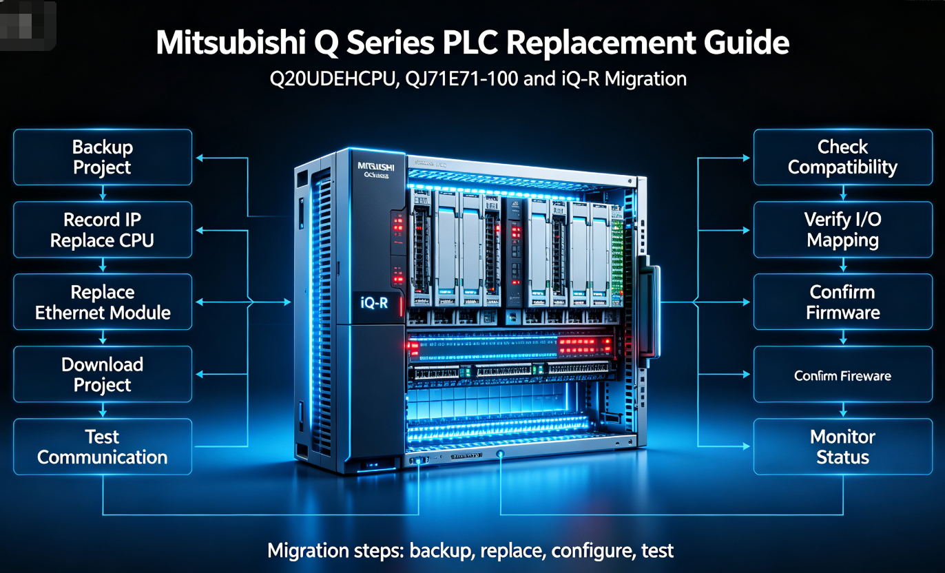
Modernization is different from emergency replacement. A newer PLC CPU or HMI platform may be better for long-term maintenance, but it may require program conversion, rack changes, network redesign, panel cutout review, cable changes and full machine validation.
Usually the safest choice when the machine is stopped and the goal is to restore operation quickly with minimum engineering change.
Better for long-term support, but requires engineering review, software migration, test plan and production validation.
Migration Checks
- Program conversion and instruction compatibility.
- HMI project conversion and tag mapping.
- Communication module and protocol support.
- I/O rack, wiring and terminal compatibility.
- Power supply and mounting changes.
- Safety, interlock and sequence validation.
- Operator training and documentation updates.
- Spare-parts strategy for the new platform.
Recommended LcdChip Parts and Content Links
LcdChip supports engineers and sourcing teams working with industrial automation spare parts, difficult-to-source modules, HMI replacement, PLC migration and machine recovery planning.
Q20UDEHCPU
Mitsubishi MELSEC-Q CPU module used in existing Q Series systems, emergency repair and spare-parts planning.
View Q20UDEHCPUQJ71E71-100
Mitsubishi Q Series Ethernet interface module commonly reviewed when PLC, HMI or SCADA communication is unstable.
Search QJ71E71-100GT2715-XTBA
GOT2000 / GT27 HMI panel used for machine visualization, alarm display, operator input and PLC communication.
View GT2715-XTBA GuideR32CPU
MELSEC iQ-R CPU often considered for modernization or migration planning from aging Q Series systems.
Search R32CPUHow to Prepare a Troubleshooting RFQ
If the machine is down and you need a replacement part quickly, include enough information for the supplier to confirm the correct model and help avoid misdiagnosis.
Recommended RFQ Information
- Machine status: stopped, intermittent fault or planned spare
- Exact suspected model number and rear-label photo
- Photos of PLC rack, HMI, communication module and wiring
- Fault symptom: black screen, CPU error, communication error, I/O failure or other
- LED status photos from CPU, communication module, power supply and I/O module
- Engineering software diagnostic message or error code
- Connected HMI model and PLC CPU model
- Communication method: Ethernet, RS-232, RS-422/485, fieldbus or other
- Program, project and parameter backup status
- Whether same-model replacement is required
- Whether used, refurbished, surplus or new condition is acceptable
- Required delivery country and deadline
- Related parts needed, such as cable, memory card, battery or terminal block
Need Help Identifying the Failed PLC, HMI or Communication Module?
Send the model numbers, label photos, LED status, fault message, wiring photos and backup status. LcdChip can help review industrial automation spare parts, including PLC CPUs, HMI panels, Ethernet modules, communication cards and discontinued control components.
View Industrial Automation Parts Search Mitsubishi PLC Parts Submit RFQFAQ: PLC CPU, HMI and Communication Module Troubleshooting
How do I know if the PLC CPU failed?
Suspect the PLC CPU if it remains in STOP or ERROR state, cannot be accessed by engineering software, repeatedly resets, reports memory or program errors, or cannot control the rack after power and wiring are verified.
Does an HMI communication error mean the HMI is broken?
Not necessarily. The cause may be the PLC CPU state, communication module, Ethernet cable, serial wiring, IP address, station number, protocol setting or HMI project configuration.
When should I suspect the communication module?
Suspect the communication module when PLC logic is running, power is stable, the HMI project is correct, but the module shows abnormal LEDs, no link, diagnostic errors or repeated communication loss.
Can a bad cable look like a failed PLC module?
Yes. A damaged Ethernet, serial or fieldbus cable can create communication errors that look like a failed HMI, PLC CPU or communication module. Test the cable and port before replacing expensive modules.
Why does the replacement PLC CPU power on but not run the machine?
The CPU may not contain the correct program, parameters, network settings or module configuration. A blank or incorrectly configured CPU can power on but still fail to control the machine.
Should I replace the HMI if the touch panel fails?
If the touch panel has local dead zones, false touch or severe surface damage, replacement may be the fastest recovery method. However, confirm the project backup, model, power type, cutout and communication ports before ordering.
What should I check before buying QJ71E71-100?
Confirm that the communication module is truly faulty by checking power, link LEDs, cable, switch port, IP settings, PLC status and HMI project settings. Also confirm the exact model and rack compatibility.
Is R32CPU a direct replacement for Q20UDEHCPU?
It should be treated as a migration option, not a simple drop-in replacement. A move from MELSEC-Q to iQ-R requires engineering review, program conversion, hardware compatibility checks and validation.