Hello! now
 tms@lcdchip.com


VOICE AI RELIABILITY ENGINEERING · FAR-FIELD AUDIO · SMART TERMINALS
A voice demo that works at 30 centimeters in a quiet office proves very little about a commercial voice product. A deployed AI terminal may need to hear a user several steps away while its own loudspeaker is playing, HVAC noise is present, other people are talking, glass surfaces are reflecting sound, and the user is standing away from the microphone's preferred direction.
That is why reliable far-field voice interaction is not primarily an ASR problem. It is a system-engineering problem involving microphone geometry, mechanical acoustics, acoustic echo cancellation, beamforming, noise suppression, wake-word tuning, barge-in behaviour, audio routing, enclosure design and measurable validation.
Stop Defining "Far Field" by One Distance Number
Far-field performance is often reduced to a statement such as "works at 3 meters" or "supports 5-meter voice pickup." That number is incomplete.
Recognition distance changes with speaker loudness, microphone sensitivity, microphone orientation, room reverberation, background noise, device playback volume, wake model, acoustic front-end tuning and enclosure geometry.
A stronger engineering requirement defines an acoustic operating envelope.
The Far-Field Signal Chain
The speech recognition engine receives the output of an acoustic system. If the upstream signal is poor, a better cloud model cannot reconstruct information that the microphones failed to capture.
Acoustic Wave
User speech + room reflections + noise + device playback.
Microphone Array
Physical capture, geometry, sensitivity and channel consistency.
AEC
Removes the terminal's own loudspeaker contribution.
Beamforming
Spatially emphasizes the intended talker.
Noise / Dereverb
Reduces interfering noise and reverberation.
Wake / ASR
Detects activation and converts speech into commands or text.
This order matters. AEC needs a clean reference to what the device is playing. Beamforming depends on multiple synchronized microphone channels. Wake-word tuning depends on the signal characteristics produced by the upstream acoustic front-end.
Microphone Geometry Is Part of the Algorithm
The microphone array cannot be selected after the industrial design is finished. Physical geometry determines what spatial information is available to the beamformer.
Linear Array
Useful when the expected user is primarily in front of a display, kiosk or wall-mounted terminal. The geometry can support directional pickup across the front interaction zone.
Best fit:Smart displays, hotel kiosks, digital humans, wall-mounted terminals.
Circular / Distributed Array
Useful when users can approach from multiple directions or when the terminal is centrally placed. Mechanical symmetry becomes important.
Best fit:Tabletop terminals, robots, meeting devices and 360-degree interaction.
Screen-Bezel Array
Microphones are integrated around or near the display bezel. This is mechanically convenient but must be checked for speaker coupling, panel vibration and large reflective glass surfaces.
Best fit:Large AI screens, mirrors, interactive signage and vertical kiosks.
Microphone Spacing: Wider Is Not Automatically Better
Microphone spacing affects the useful spatial information available for directionality. An array that is too compact may provide weak directional discrimination at some frequencies. An array that is too wide can create ambiguity at higher frequencies and becomes more sensitive to mechanical mismatch.
The correct spacing therefore depends on the acoustic algorithm, target speech band, enclosure size, user direction and microphone topology.
Confirm the geometry with the acoustic algorithm or DSP provider.
Different gain, delay or filtering between microphone channels damages array processing.
A bare microphone PCB does not represent performance behind glass, plastic, mesh and gaskets.
Array algorithms assume microphone position and channel behaviour stay within reasonable production variation.
Mechanical Acoustics Can Destroy an Excellent Microphone Array
A good microphone, codec and DSP can still produce poor results after the board is installed in the final enclosure. Mechanical design modifies the acoustic path before software sees the signal.
| Mechanical Detail | Potential Failure | Design Review Question |
|---|---|---|
| Microphone port | Attenuation, frequency coloration or blocked pickup | Is the opening aligned with the microphone and free from internal obstruction? |
| Mesh / membrane | High-frequency loss or channel mismatch | Has the real acoustic material been included in validation? |
| Internal cavity | Resonance and coloration | Does the microphone sit behind a cavity that creates resonant behaviour? |
| Glass front | Strong reflections and reverberation | Is the microphone too close to a large reflective surface? |
| Speaker location | High echo energy into microphones | Can physical separation or isolation reduce the echo path before DSP? |
| Cooling fan | Continuous tonal or broadband noise | Does the fan couple acoustically or mechanically into the mic structure? |
| Panel vibration | Structure-borne noise | Does loudspeaker or touch interaction vibrate the microphone mounting region? |
| Seal / gasket tolerance | Unit-to-unit acoustic inconsistency | Can assembly variation change the microphone's acoustic path? |
AEC: The Foundation of Barge-In
Acoustic Echo Cancellation becomes critical when a terminal must hear the user while its own loudspeaker is active. The loudspeaker output is normally much stronger at the microphone than a distant human voice.
AEC uses a reference signal corresponding to the audio being sent toward the loudspeaker and estimates how that audio propagates through the speaker, enclosure and room back into the microphones. The estimated echo component is then removed from the microphone signal.
Barge-In Is Harder Than "AEC Enabled"
Barge-in means the user can interrupt the terminal while TTS, music or another audio stream is playing. This creates a double-talk condition: both the device and the user speak at the same time.
A production barge-in design must therefore evaluate more than whether an AEC API exists.
Beamforming: Improve Spatial Selectivity Without Treating It as Magic
Beamforming combines the phase and amplitude information from multiple synchronized microphones to emphasize sound from selected directions and suppress interfering directions.
Its effectiveness depends on array geometry, frequency, synchronization, room reflections, competing talkers and algorithm design.
What Beamforming Can Help
- Improve desired-speech SNR
- Reject directional interference
- Support talker-direction estimation
- Improve far-field wake reliability
- Reduce some room-noise contribution
What Beamforming Cannot Fix Alone
- Blocked microphone ports
- Severe clipping
- Broken microphone channels
- Bad AEC reference
- Extreme reverberation
- Poorly positioned loudspeakers
For smart displays, the desired beam strategy should match the product interaction zone. A wall display with users directly in front does not necessarily need the same array or beam search strategy as a service robot approached from multiple directions.
Noise Is Not One Test Condition
Saying "tested in noise" is insufficient. Different noise classes stress different parts of the voice pipeline.
Steady Broadband Noise
HVAC, airflow and ventilation. Useful for testing noise suppression and long-duration stability.
Point Noise
Printer, fan, appliance or machine located in one direction. Useful for spatial rejection testing.
Competing Speech
Nearby people talking. One of the hardest conditions for wake-word and ASR systems.
Device Playback
TTS, advertisements, music or video from the terminal itself. Primarily stresses AEC and barge-in.
Transient Noise
Door slam, object impact, keyboard, trolley or sudden mechanical noise. Useful for false-wake testing.
Reverberant Field
Large glass, tile or concrete spaces. Stresses spatial processing and endpoint detection.
False Wake and Missed Wake Must Be Optimized Together
Wake-word tuning is a threshold trade-off. Making the detector more sensitive may reduce missed activations but increase false wake-ups. Making it more conservative may reduce false activation while frustrating real users.
False Reject / Missed Wake
User says the correct wake word but the terminal does not activate.
- Low speech level
- Accent mismatch
- Noise
- Off-axis user
- Overly strict threshold
False Acceptance / False Wake
The terminal activates without an intended wake command.
- Similar phrases
- TV or advertising audio
- Device TTS
- Background conversation
- Overly sensitive threshold
For a public kiosk, one false wake every few minutes can make the product appear unstable. For a hands-free accessibility product, excessive missed wakes may be even more damaging. Acceptance criteria must therefore reflect the real application.
Use a Wake-Test Corpus, Not Only Engineer Voices
A production validation set should include multiple speakers and realistic negative audio. Testing with the same engineers who tuned the system creates an artificially easy benchmark.
Different genders, ages, accents, speech levels and speaking speeds.
Cover the intended interaction zone, not just the best position.
Front, left, right and any permitted off-axis user position.
Similar-sounding words and normal conversation without the wake phrase.
TV, music, advertisements, TTS and video with speech.
Real or representative target deployment noise.
Android AEC and Noise Suppression: Validate the Actual Device
Android exposes Acoustic Echo Canceler and Noise Suppressor interfaces, but product software should not assume that every platform implements them identically or even provides them.
A production application should check capability at runtime, verify which processing path is active for the selected AudioRecord session, and then validate performance acoustically on the actual BSP and hardware revision.
API Available?
Confirm the platform reports that the required effect exists.
Effect Enabled?
Creating an effect object does not by itself prove production behaviour.
Correct Audio Session?
Verify processing is attached to the capture path used by the application.
Acoustic Performance?
Measure residual echo, barge-in and recognition results on the complete product.
Dedicated Voice DSP vs Application-Processor AFE
A voice terminal can implement acoustic processing in several places: inside the application processor, inside a dedicated voice DSP, inside an audio codec with DSP features, or through a separate microphone-array module.
| Architecture | Advantages | Trade-Offs | Best Fit |
|---|---|---|---|
| Application processor | Flexible software, fewer dedicated chips, easier integration with app logic | CPU load, BSP dependency, tuning and real-time scheduling requirements | Integrated AI terminal with sufficient processing headroom |
| Dedicated voice DSP | Deterministic AFE, isolated audio workload, mature far-field stack options | Added BOM, firmware integration and signal routing | Premium far-field, high playback level or demanding acoustic environments |
| Smart audio codec / DSP | Compact integration and audio-path specialization | Feature set and microphone topology may be constrained | Mid-complexity voice products |
| External mic-array module | Fast prototyping and acoustic solution reuse | Mechanical fit, cost and vendor dependency | Prototype, low-volume equipment and rapid development |
Do Not Size the Edge Hardware from the Wake Engine Alone
A modern smart terminal may run voice processing concurrently with 4K graphics, camera capture, vision AI, cloud networking, local database, TTS, Bluetooth and peripheral control.
CPU Budget
AFE, audio routing, ASR client, UI, networking and business application.
NPU Budget
Vision AI, local models or supported voice inference workloads.
Memory Budget
Audio buffers, camera buffers, ASR assets, AI models and application memory.
Audio I/O
Enough synchronized microphone channels and playback/reference paths.
Network Budget
Voice cloud traffic may compete with video, OTA and business APIs.
Thermal Budget
Sustained voice + display + vision workload must remain stable inside the enclosure.
RK3576-Class Hardware for Voice + Vision + Display Terminals
For multimodal products, RK3576-class platforms are relevant because the terminal may need display, camera, edge AI, audio processing, network connectivity and industrial I/O on one system.
The correct integration path depends on the required microphone topology. A base AI terminal board may provide standard microphone and speaker interfaces, while a true multi-microphone far-field implementation may require a customized carrier board, digital microphone interface, codec or dedicated acoustic DSP.
Use for Android/Linux, display, camera, networking, application logic and local AI workloads.
Add the microphone topology, codec/DSP, reference routing and speaker architecture needed by the product.
Tune the array only after enclosure, speaker, microphone ports and installation geometry are stable.
Far-Field Voice Failure Tree
Problem: Wake Range Is Too Short
- Blocked or poorly placed microphone
- Low microphone sensitivity
- AFE gain problem
- Noise suppression too aggressive
- Wake threshold too conservative
- Array geometry mismatch
Problem: Barge-In Fails
- AEC reference mismatch
- Playback clipping
- Speaker too close to microphones
- Echo path changes
- Double-talk handling weakness
- Wake model sees residual TTS
Problem: False Wake Is High
- Threshold too sensitive
- Similar phonetic phrases
- Media content triggers engine
- AEC residual echo
- Insufficient negative corpus
- Wrong environment tuning
Problem: One Production Unit Performs Worse
- Dead microphone channel
- Mic sensitivity mismatch
- Gasket assembly variation
- Blocked acoustic port
- Speaker or amplifier variation
- Wrong firmware/tuning package
Acoustic Validation Should Use Gates, Not One Final Demo
Electrical Audio Bring-Up
All microphone channels, speaker path, codec clocks, gains and channel mapping verified.
Open-Board Acoustic Test
Baseline AFE, wake and barge-in performance before enclosure effects.
Final Enclosure Test
Real microphone ports, mesh, display glass, speaker and mechanical construction.
Environmental Test
Realistic distance, noise, user angle, reverberation and playback conditions.
Long-Run Multimodal Test
Voice + camera + display + AI + network running concurrently.
Production Correlation
Define factory measurements that correlate with the validated golden unit.
Recommended Far-Field Voice Validation Matrix
The exact numbers should be chosen for the product, but the matrix below shows how the test plan should be structured.
| Variable | Test Levels | Primary Metrics |
|---|---|---|
| User distance | Near, nominal and maximum design distance | Wake success, command success, ASR quality |
| User angle | Front and permitted off-axis positions | Wake success, DoA stability where applicable |
| Background noise | Quiet, nominal deployment noise, worst-case design noise | Wake success, false reject, command success |
| Device playback | Mute, normal TTS level, maximum permitted level | Barge-in success, residual echo, false wake |
| Noise type | HVAC, music, competing speech, point noise, transient noise | Wake/ASR robustness by noise class |
| Language / accent | Supported production languages and target user accents | Wake and command success |
| Network state | Normal, degraded, offline | Local response and fallback behaviour |
| Thermal state | Cold start, nominal, sustained full workload | Latency and recognition stability |
Useful Engineering Metrics
Wake Success Rate
Valid wake attempts successfully accepted under a defined acoustic condition.
False Wake Rate
Unintended activations during a defined negative-audio test duration.
False Reject Rate
Intended wake attempts incorrectly rejected.
Command Success Rate
Spoken commands that result in the correct intended action.
Word Error Rate
Useful for controlled ASR transcription benchmarking.
ERLE / Residual Echo
Useful internal AEC metrics when supported by the selected audio stack.
Barge-In Success
Successful wake/command operation while the device speaker is active.
End-to-End Latency
Time from user activation/speech to visible or audible system response.
Unit-to-Unit Variation
Performance distribution across pilot and production hardware, not one golden unit.
Production Test: A Simple Audio Loopback Is Not Enough
Factory testing cannot reproduce the full acoustic laboratory for every unit, but it should detect assembly defects that would destroy far-field performance.
Microphone Presence
Detect dead or disconnected microphone channels.
Channel Mapping
Verify microphone channels are connected to the expected array positions.
Sensitivity Window
Identify microphones or acoustic ports with abnormal response.
Speaker Output
Confirm speaker and amplifier path before final assembly release.
Reference Path
Verify the playback reference required by AEC is present and correctly routed.
Firmware / Tuning ID
Record AFE, wake model and application versions for traceability.
For higher-volume products, acoustic stimulus and microphone-response comparison against a validated golden sample can provide stronger production screening than digital loopback alone.
Application Profiles: Different Products Need Different Acoustic Designs
AI Digital Human Screen
Primary challenge: large display glass + loud TTS + public-space noise.
Priority: strong AEC, front-zone beamforming, barge-in and multilingual wake validation.
Smart Fitness Mirror
Primary challenge: reflections, music playback, user movement and increased interaction distance.
Priority: loud-playback barge-in and robust moving-user coverage.
Service Robot
Primary challenge: 360-degree users, motor/fan noise and changing orientation.
Priority: distributed/circular array strategy, DoA and mechanical-noise isolation.
Hotel / Retail Kiosk
Primary challenge: competing speech, background music and multilingual users.
Priority: false-wake control, front-zone pickup and strong fallback UI.
Healthcare Terminal
Primary challenge: intelligibility, privacy and user variation.
Priority: controlled listening states, clear UI and repeatable near/mid-field recognition.
Industrial Voice HMI
Primary challenge: machinery noise and safety-sensitive commands.
Priority: limited vocabulary, confirmation logic and conservative acceptance criteria.
How LcdChip Can Position Far-Field Voice Hardware Projects
For LcdChip, this topic should not be promoted as "we sell a motherboard with microphone input." That is too weak and technically incomplete.
A stronger position is: AI terminal hardware platform + customized audio front-end + display/camera/network integration + production validation support.
AI Terminal Compute
Android/Linux, application processing, display, camera, network and edge AI.
Voice Front-End
Project-specific microphone array, codec/DSP, AEC reference path and speaker integration.
Product Acoustic Design
Microphone ports, enclosure, array geometry, speaker placement and acoustic tuning.
Validation
Wake, false wake, barge-in, noise, distance, angle and production correlation.
Recommended Internal Links
Far-Field Voice RFQ Engineering Pack
For far-field voice projects, a useful RFQ must include the acoustic environment. A motherboard model alone is not enough.
- Application: digital human, smart mirror, kiosk, robot, medical terminal, HMI or custom equipment
- Expected user distance range
- Expected user angle / coverage zone
- Target languages and accents
- Wake word and command strategy
- Allowed false-wake and missed-wake behaviour
- Microphone count preference or mechanical constraints
- Available microphone mounting positions
- Enclosure material, front glass and acoustic openings
- Speaker quantity, location and maximum playback level
- Required barge-in behaviour
- Target background-noise environment
- Expected room characteristics and reverberation
- Dedicated DSP / codec / mic-array module preference, if any
- Analog mic, PDM, I²S/TDM or other audio-interface requirement
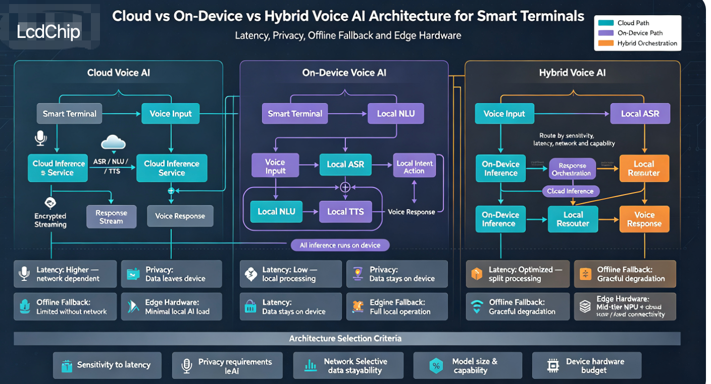
- Local wake / local ASR / cloud ASR architecture
- Display and touch requirement
- Camera / vision AI requirement
- Android or Linux requirement
- Network and cloud-AI requirement
- Power and thermal constraints
- Production volume
- Factory acoustic-test expectation
- Target validation metrics and acceptance criteria
Design the Acoustic System Before Freezing the Terminal Hardware
Send the target interaction distance, microphone positions, speaker layout, noise environment, wake word, language, enclosure, display, camera, AI workload and production requirements. LcdChip can evaluate the AI terminal platform and customized audio hardware path for voice + vision + display products.
Evaluate RK3576 AI Terminal Hardware Submit Voice AI RFQFAQ: Far-Field Voice Interaction Engineering
What is far-field voice recognition?
Far-field voice recognition describes voice interaction where the user speaks from a meaningful distance rather than directly into a microphone. Practical performance depends on distance, angle, noise, room acoustics, microphone geometry and device playback conditions.
How many microphones are needed for far-field voice?
There is no universal microphone count. The required topology depends on coverage area, interaction distance, enclosure geometry, noise field and the selected beamforming/AEC solution.
What is barge-in?
Barge-in is the ability for a user to speak to or interrupt the terminal while the terminal's own speaker is playing audio. Reliable barge-in normally requires effective echo cancellation and double-talk handling.
Why does AEC need a playback reference?
AEC estimates the echo created by the device's own loudspeaker. A reference corresponding to the playback signal helps the algorithm identify what portion of the microphone input originates from the terminal itself.
Does Android AEC guarantee far-field performance?
No. Platform support and implementation vary. Availability should be checked on the actual device, and acoustic performance must be validated on the real hardware, BSP and enclosure.
Why can a voice system work on an open board but fail inside the enclosure?
The enclosure changes microphone ports, reflections, resonance, speaker coupling, mechanical vibration and channel consistency. Acoustic tuning should therefore be validated after the mechanical design is representative.
What should be measured before mass production?
Useful metrics include wake success, false wake, false reject, command success, barge-in success, ASR quality, latency, residual echo and unit-to-unit acoustic variation.