The Rotary Knob Squeeze: Driving Circular LCDs on a $2 MCU Budget
The Industrial Design vs. BOM Cost War
Here is a classic hardware development meeting. The Industrial Design (ID) team presents a rendering of your company's next-generation smart thermostat. It features a sleek, mechanical rotary knob with a vibrant, 60FPS circular LCD embedded right in the center, mimicking the fluid UI of a high-end smartwatch.
Then the purchasing department chimes in: "Great. But the entire MCU budget is $2.00. You have to run this on a Cortex-M0 or an ESP32."
As the hardware engineer, you are now caught in the crossfire. You cannot throw a $15 Linux-capable MPU with a dedicated MIPI DSI interface at a simple smart home appliance. You have to achieve buttery-smooth graphical rotations on a 1.28-inch circular screen using a low-cost microcontroller and a serial interface. Let's look at the hardware realities of making this work without the screen tearing or choking the CPU.
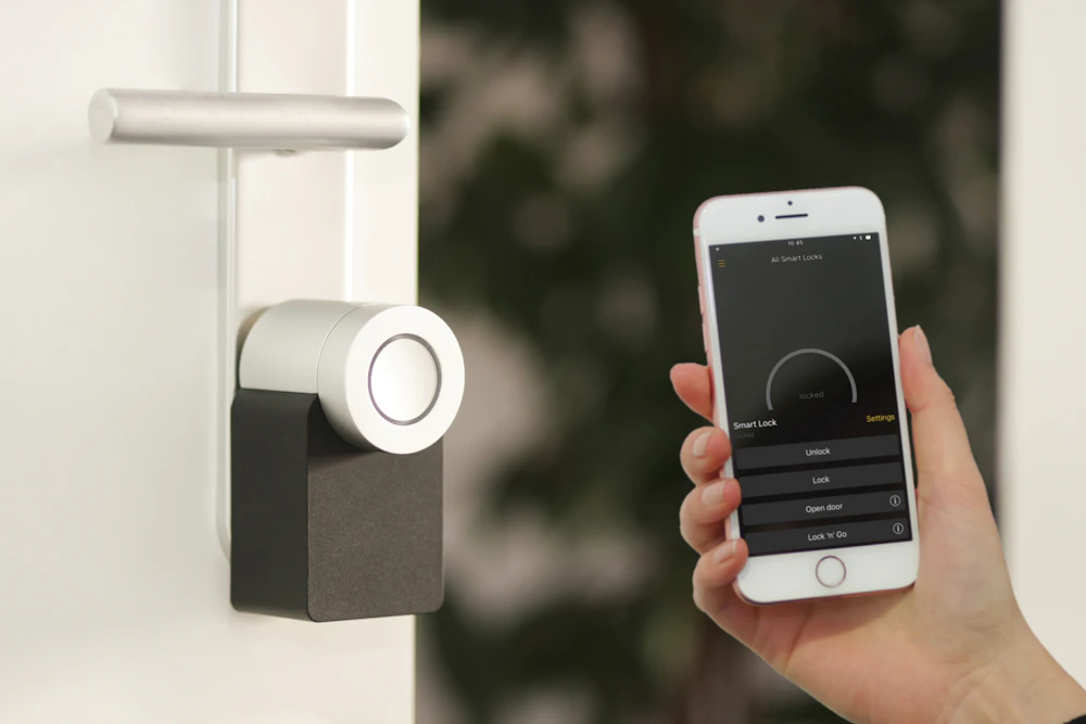
The mechanical rotary knob with an embedded display is the new gold standard for Smart Home HMI, but it puts massive strain on low-cost microcontrollers.
1. The "Square Peg, Round Hole" Memory Tax
The first shock most junior engineers get when working with circular displays is the memory architecture. A circular LCD (like the popular 1.28" 240x240 panels) is not physically addressed as a circle. The underlying TFT matrix and the driver IC's Graphic RAM (GRAM) still map out a square.
This means your MCU still has to calculate, buffer, and transmit the pixels for the "invisible" corners that physically exist outside the circular glass cut-out.
The Bench Fix: If your MCU is tight on SRAM, do not allocate a full-frame buffer (which would cost ~115KB for a 240x240 RGB565 screen). Instead, you must use partial rendering techniques (often supported by embedded graphic libraries like LVGL). You break the UI down into smaller horizontal bands, rendering and pushing only 10 to 20 lines of pixels over the bus at a time. This keeps your MCU RAM usage under 10KB while still achieving fluid animations.
2. The Bandwidth Bottleneck: SPI vs QSPI
When the user spins the physical knob, the UI needs to rotate instantly. If there is a lag between the mechanical click of the rotary encoder and the visual update, the appliance feels cheap.
If you are using standard 4-wire SPI, achieving 60FPS on a 240x240 screen requires a theoretical bandwidth of around 55 Mbps. Most low-cost MCUs cap their SPI peripherals at 40 Mbps. If you try to push full-screen UI rotations over standard SPI, you will inevitably drop frames.
The Hardware Architecture Solution:
- Internal GRAM is Non-Negotiable: You must select a display driver IC (like the GC9A01 or specific Sitronix ST7789 variants) that features integrated GRAM. This allows the driver IC to continuously refresh the panel independently, freeing up the MCU to only transmit the pixels that actually changed.
- Upgrade to QSPI or MCU 8-bit: If your BOM allows it, specify an LCD module with a Quad-SPI (QSPI) interface. By utilizing four data lines instead of one, you effectively quadruple your bandwidth, easily maintaining 60FPS fluid animations even on an ESP32-S3 or STM32G0.

Achieving high frame rates on a budget requires careful balancing of the MCU's DMA capabilities and the display driver IC's internal Graphic RAM.
3. Defeating the Diagonal Tear
There is nothing worse than watching a beautiful circular dial animation suffer from a diagonal "tear" right across the middle of the glass. Screen tearing happens when your MCU writes new pixel data to the driver IC's GRAM at the exact same moment the driver IC is reading that RAM to refresh the glass.
Because circular UIs involve heavy rotational math, tearing is far more visually jarring than it is on a standard square display.
The Hardware Fix (The TE Pin): Never leave the TE (Tearing Effect) pin floating. Ensure the LCD module you source exposes the TE pin, and route it directly to an external interrupt pin on your MCU. This pin pulses high during the "Vertical Blanking" period-the brief window when the LCD driver is not actively painting the screen. Configure your MCU's DMA controller to only flush pixel data over the SPI bus when the TE interrupt triggers. This guarantees your visual rotations are perfectly synchronized with the glass refresh rate.
Source the Right Silicon for the Job
Designing a rotary knob display on a tight budget is entirely possible, but you cannot afford to brute-force it with software. You have to select a display module and driver IC architecture that works *with* your MCU, rather than fighting against its bandwidth limits.
If you are currently struggling to optimize a circular display for your next smart home appliance, you might be using the wrong silicon. At LCDChip, we specialize in supplying high-performance, low-power circular LCD modules specifically architected for rotary knob integration.
We stock industry-standard driver ICs equipped with deep internal GRAM and QSPI support to ensure your UI remains buttery smooth, even on the cheapest microcontrollers. Contact our engineering team today to request a sample of our 1.28" or 2.1" rotary display solutions and get access to our verified initialization code.
Related information


