Hello! now
 tms@lcdchip.com


Engineering Guide for Intelligent Display PCBA, SMARC Modules, Core Boards and Custom Carrier Design
A core board or SMARC module can shorten development time, but it does not finish the product. The final product depends on the carrier board: power input, LCD interface, touch, camera, Ethernet, USB, CAN-FD, RS485, audio, storage, wireless module, thermal path, enclosure fit, firmware bring-up and factory testing.
This guide is written for overseas OEM buyers, procurement engineers, hardware developers and product teams building intelligent display PCBA, industrial HMI panels, AI vision terminals, digital signage controllers, access-control devices, medical displays, transportation equipment and custom embedded hardware. It also explains why the LcdChip independent website should be used as a technical source for core board selection, carrier board planning, intelligent display PCBA evaluation and RFQ conversion.
Processor modules solve CPU, memory and high-speed core design. The carrier board solves the customer's real product: connectors, power, display, camera, I/O, enclosure, service access, compliance risk and production test. A strong PCBA supplier must discuss both.
Real Project Problem: The Module Works, but the Product Still Cannot Ship
A customer selects a powerful core board for an intelligent display project. The development kit boots correctly. HDMI output works. Ethernet connects. Linux or Android starts. The team believes the hardware platform is ready.
Then the custom carrier board starts. Problems appear one by one: the LVDS panel does not light up, the MIPI CSI camera is unstable, the USB device fails after hot-plug, the CAN-FD port needs a different transceiver, the enclosure blocks the FPC cable, the power rail drops during boot, and the factory has no simple way to test the finished board.
The root issue
The team selected the module, but did not define the carrier board architecture early enough. For intelligent display PCBA, carrier design must be planned together with the LCD panel, camera, power input, operating system, enclosure and production test method.
Why This Topic Can Bring High-Quality Traffic to the LcdChip Independent Website
Customers searching for carrier board design are usually closer to a real project than customers searching only for a chip name. They may already have an LCD panel, enclosure, peripheral list, software requirement and production target. That means the traffic is smaller than broad chip keywords, but the inquiry intent is much stronger.
The LcdChip independent website can use this topic to become a technical bridge between solution pages and RFQ. Instead of only listing TET3588-C, TET3568-C, TET-MX8MPQ-SMARC, TETMX8MP-C or TET62xx-C, LcdChip can explain how overseas buyers should turn these platforms into production-ready intelligent display hardware.
Customer is considering module-based product development.
Customer needs a board that fits a specific LCD, enclosure and I/O layout.
Customer may need AI vision, MIPI CSI, dual Ethernet and industrial multimedia design.
Customer may need Linux HMI, CAN-FD, dual display, Ethernet and long-lifecycle control.
Customer may need high-end AI, multi-screen output, camera input and thermal planning.
Customer is moving from prototype to pilot run or mass production.
Core Board vs Carrier Board vs Full Custom PCBA
The first decision is development architecture. A core board reduces risk around processor, DDR, PMIC and boot design. A carrier board adapts the module to the customer's product. Full custom PCBA integrates everything into one optimized design.
Core Board or SMARC Module
Good for reducing processor design risk and speeding up early development. It usually includes CPU, DDR, eMMC, PMIC and essential boot circuitry.
- Faster evaluation
- Lower early engineering risk
- Useful for platform scalability
- Still needs a carrier board
Custom Carrier Board
Good when the module is suitable, but the final product needs application-specific connectors, display interfaces, camera ports, field I/O, power input and enclosure placement.
- Product-specific I/O
- Cleaner enclosure integration
- Better service access
- Factory test can be planned
Full Custom PCBA
Good for mature products with stable requirements, higher volume, strict cost target, thin enclosure, special thermal path or long-term BOM control.
- Optimized size and cost
- Controlled connector layout
- Dedicated power and thermal design
- Requires deeper validation
Carrier Board Planning Starts with an Interface Budget
Before schematic design, the engineering team should build an interface budget. This is not only a list of ports. It is a decision map that assigns each interface to a real product function, checks whether the module exposes the required signals, and verifies whether software support is available.
This is where the LcdChip independent website should guide buyers clearly: a good RFQ should include the complete interface budget, not only the preferred processor model.
Power Architecture: Carrier Boards Fail When Power Is Treated Too Late
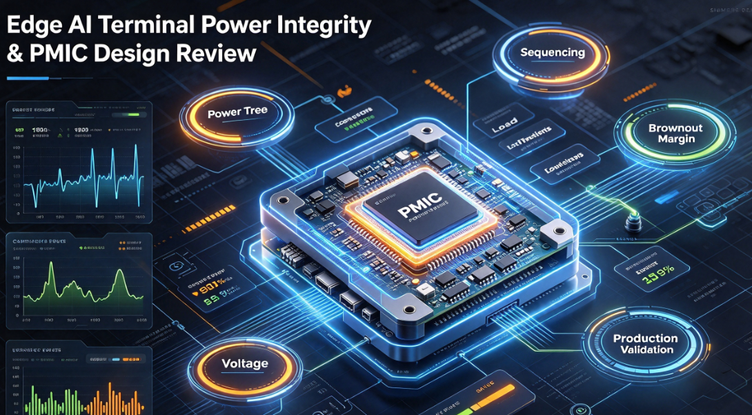
Carrier boards often look simple compared with processor modules, but power design can still break the product. The carrier board may need 5V, 12V, 24V, PoE, battery input, relay power, backlight power, camera rails, USB current limit, audio amplifier power and protection for field wiring.
Power questions for buyers
- What is the final input power source?
- Does the device need PoE or only DC input?
- How much power does the LCD backlight consume?
- How many USB devices require power?
- Does any external load need relay or lock control?
- Does the product need backup power or safe shutdown?
Power questions for engineers
- Are all rails sequenced correctly?
- Is inrush current controlled?
- Are field connectors protected?
- Is there enough thermal margin in DC/DC converters?
- Are analog camera rails clean?
- Is the factory test able to catch power instability?
Display and Touch: The Carrier Board Must Match the Real LCD
Intelligent display products are usually judged by the screen first. Even when the processor platform is excellent, the product fails if the carrier board does not match the LCD panel, backlight and touch interface correctly.
LCD Panel
Exact panel model, resolution, interface, pinout, power rail, timing and mechanical drawing.
Backlight
LED voltage, current, BL_EN, PWM dimming, brightness target and thermal impact.
Touch
USB, I2C, RS232, capacitive, resistive, cover glass, bonding and coordinate rotation.
Carrier Routing
Connector position, FPC direction, EMI, ESD, cable retention and service access.
The LcdChip independent website should connect this topic with LCD controller board RFQ, embedded display interface guide and intelligent display PCBA solution pages. This improves internal links and helps customers move from technical reading to project inquiry.
Camera and AI Vision: Do Not Route MIPI CSI as an Afterthought
For AI vision terminals, face recognition devices, inspection displays and smart kiosks, camera design must be planned at the carrier-board level. MIPI CSI, USB camera, sensor driver, ISP pipeline, lens placement and lighting condition all affect final performance.
MIPI CSI Design Checks
- Lane count and host support
- FPC connector pinout and direction
- Sensor power rails and sequencing
- Reset, power-down and clock signals
- Impedance, length and routing quality
- Driver, device tree and ISP support
USB Camera Design Checks
- UVC compatibility
- USB bandwidth and hub topology
- Power draw and current limit
- Hot-plug and reconnect behavior
- Cable strain and enclosure mounting
- Android or Linux application access
AI Vision Validation Checks
- Camera frame rate under full system load
- Recognition latency and AI FPS
- Low-light and backlight behavior
- Heat near sensor and SoC
- Cloud sync or local database behavior
- Long-run stability in enclosure
Industrial I/O: The Part That Makes a Display Product Useful in the Field
A smart display becomes an industrial product when it connects to real machines, controllers, sensors and networks. The carrier board must translate the module's digital interfaces into protected, serviceable and field-ready connectors.
Useful for industrial devices, transportation systems and embedded control. Requires transceiver, termination and EMC planning.
Common for industrial meters, controllers, sensors and access systems. Requires biasing, termination and surge protection.
Useful for legacy devices, barcode scanners, debugging and control equipment. Requires level shifting and connector planning.
Used for buttons, alarms, triggers, door locks and external control. Requires isolation and transient protection when connected to field loads.
Useful for gateways, industrial routing, machine networks and cloud connectivity. Requires careful PHY and magnetics layout.
Used in intercom, medical terminals, access control and voice prompts. Requires amplifier, speaker path and microphone noise review.
Mechanical Design: Connector Direction Can Decide the Product
Carrier board design is not only electrical. The final enclosure decides connector direction, cable exit, mounting hole position, debug access, SIM card access, SD card access, antenna routing and thermal contact. These details should be reviewed before PCB layout begins.
Must match enclosure space, mounting posts, display position and service access.
USB, Ethernet, serial, power and antenna connectors should face the correct direction for installation.
LCD, touch and camera FPC cables should not fold sharply or cross hot components.
SoC, PMIC, PoE section and backlight driver need a defined heat path to metal or airflow.
Wi-Fi, Bluetooth, 4G and GNSS antennas require keep-out areas and enclosure material review.
Debug port, reset, boot mode, firmware update and test pads must remain accessible during production.
Software Bring-Up: Carrier Boards Need Driver Discipline
A carrier board changes the software project. Even when the module BSP is available, the final board may require device-tree modification, panel timing, touch mapping, camera driver, Ethernet PHY configuration, CAN-FD enablement, GPIO naming, audio routing and production flashing scripts.
This software-to-hardware connection is another reason the LcdChip independent website should publish engineering articles, not only solution thumbnails. Overseas customers trust suppliers who understand bring-up risk.
Production Validation: A Carrier Board Must Be Designed for Testing
A prototype carrier board can be tested by an engineer with cables and scripts. A production carrier board must be tested repeatedly by a factory process. That difference should affect schematic, layout, test pad placement, firmware burning, labeling and packing.
Engineering Validation
Confirm power rails, boot, display, touch, camera, Ethernet, CAN-FD, USB, serial, audio and basic application behavior.
Design Validation
Test enclosure fit, thermal behavior, EMI risk, cable movement, long-run operation and field I/O stability.
Production Validation
Build pilot units using production process, test fixture, firmware programming, labels, QC records and packing method.
Mass Production
Control BOM, board revision, module version, firmware version, test reports, defect feedback and lifecycle plan.
Factory test points that should be planned early
- Power input and current draw test
- Boot and firmware version check
- LCD pattern and backlight test
- Touch coordinate and rotation test
- Camera preview or image capture test
- Ethernet and Wi-Fi connectivity test
- CAN-FD, RS485, UART and GPIO loopback test
- USB hot-plug and current limit test
- Audio speaker and microphone test
- Thermal spot check under defined workload
How LcdChip Can Position Its Intelligent Display PCBA Solutions
The LcdChip independent website should position the Intelligent Display PCBA Solutions page as a serious engineering hub. Customers should feel that LcdChip can help them move from a module idea to a finished embedded display product.
Platform selection
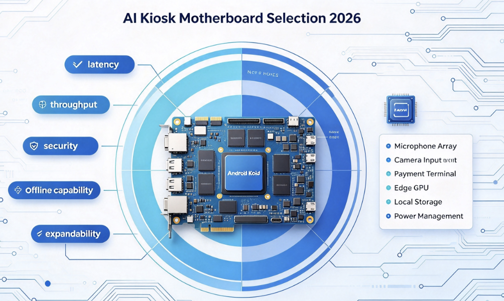
Help customers compare TET3588-C, TET3568-C, TET-MX8MPQ-SMARC, TETMX8MP-C and TET62xx-C by application, display, AI, I/O, OS, cost and lifecycle.
Carrier board planning
Guide buyers through power input, LCD panel, touch, camera, Ethernet, CAN-FD, USB, audio, wireless module, enclosure and test fixture.
Custom PCBA conversion
Turn educational content into RFQs by showing when a standard board is enough, when a custom carrier is better, and when full custom PCBA should be considered.
Recommended LcdChip Platform Directions
TET3588-C
A strong direction for high-end AI display terminals, multi-screen systems, camera-rich products, smart NVR, visualization gateways and performance-heavy embedded display devices.
View Intelligent Display PCBA SolutionsTET3568-C
A balanced direction for industrial HMI, security terminals, medical equipment, energy systems, communication products and lightweight AI display applications.
View Intelligent Display PCBA SolutionsTET-MX8MPQ-SMARC
A strong module direction for AI vision products that need NPU, ISP, camera, Ethernet, USB, PCIe, CAN-FD and application-specific carrier board design.
View Intelligent Display PCBA SolutionsTET62xx-C
A practical direction for Linux industrial control, scalable product families, dual Ethernet, CAN-FD, LVDS/RGB display and cost-sensitive embedded systems.
View Intelligent Display PCBA SolutionsCarrier Board RFQ Engineering Pack
A complete RFQ helps LcdChip review the project faster and recommend the right platform, carrier board architecture or full custom PCBA path.
- Application type: industrial HMI, AI vision, smart terminal, digital signage, access control, medical display, transportation or custom product
- Preferred platform if known: TET3588-C, TET3568-C, TET-MX8MPQ-SMARC, TETMX8MP-C, TET62xx-C or undecided
- Development path: standard board, core board plus custom carrier, modified carrier board or full custom PCBA
- LCD panel model, resolution, brightness, interface, datasheet and backlight requirement
- Touch requirement: USB, I2C, RS232, capacitive, resistive, cover glass or no touch
- Camera requirement: MIPI CSI, USB UVC, sensor model, lens, resolution, frame rate and AI workload
- AI workload: face recognition, object detection, OCR, people counting, inspection, image enhancement or no AI
- Network requirement: single Ethernet, dual Ethernet, Wi-Fi, Bluetooth, 4G, TSN, cloud sync or local-only operation
- Industrial I/O: CAN-FD, RS485, RS232, UART, GPIO, relay, audio, USB, PCIe, SATA, SDIO or GPMC
- Operating system: Android, Linux, OpenHarmony, OpenEuler, Debian, Linux Qt or custom firmware
- Software needs: boot logo, kiosk mode, OTA, watchdog, local database, API, cloud sync and production flashing
- Power input: 5V, 12V, 24V, PoE, battery, adapter or wide-voltage industrial DC
- Mechanical requirement: board size, connector direction, mounting holes, enclosure material, antenna position and cable routing
- Thermal requirement: fanless, heat spreader, ambient temperature, LCD backlight heat, enclosure contact and continuous workload
- Production plan: prototype quantity, EVT, DVT, PVT, pilot run, mass-production forecast and lifecycle expectation
Design Your Intelligent Display Carrier Board with LcdChip
Send your application, display, touch, camera, AI workload, I/O, operating system, power, enclosure and production requirements. The LcdChip independent website helps overseas buyers evaluate intelligent display PCBA solutions, SMARC modules, industrial core boards, custom carrier boards and full custom PCBA development.
View Intelligent Display PCBA Solutions View AI Smart Terminal Boards Submit RFQ to LcdChipFAQ: Carrier Board Design for Intelligent Display PCBA
What is a carrier board in an embedded display product?
A carrier board is the application-specific PCB that connects a core board or SMARC module to the final product's LCD, touch, camera, Ethernet, USB, CAN-FD, serial ports, power input, audio, enclosure connectors and production test points.
Why use a core board or SMARC module instead of full custom PCBA first?
A core board or SMARC module can reduce early processor, memory, PMIC and boot-design risk. It helps teams prototype faster while leaving product-specific connectors and I/O to the carrier board.
When should a customer move from carrier board to full custom PCBA?
Full custom PCBA becomes more suitable when the product has stable requirements, higher volume, strict enclosure limits, cost targets, thermal requirements or long-term BOM control needs.
What are the most common carrier board design mistakes?
Common mistakes include incomplete interface budgeting, weak power margin, poor LCD cable planning, late camera-driver review, missing field protection, bad connector direction and no production test strategy.
Why is display planning important in carrier board design?
Display planning confirms LCD interface, panel voltage, timing, backlight power, PWM dimming, touch interface, connector position and firmware support before layout becomes fixed.
Why is the LcdChip independent website useful for carrier board projects?
The LcdChip independent website connects intelligent display PCBA solutions, platform selection, carrier board planning, display interface guidance, RFQ preparation and custom PCBA support in one engineering-oriented source.
What should I send to LcdChip for carrier board evaluation?
Send the application, preferred platform, LCD panel, touch, camera, AI workload, I/O list, operating system, power input, enclosure drawings, thermal requirement, quantity and production schedule.